Wheel balance weight

a technology of balance weight and wheel, applied in the direction of wheel balance weight, mechanical equipment, transportation and packaging, etc., can solve the problems of wheel imbalance, vibration and noise, vibration and noise, etc., and achieve the effect of reducing vibration and nois

Inactive Publication Date: 2011-01-20
TAIHO INDUSTRIES CO LTD +1
View PDF10 Cites 5 Cited by
  • Summary
  • Abstract
  • Description
  • Claims
  • Application Information

AI Technical Summary

Problems solved by technology

In such a wheel-assembled state that a tier of an automobile, or the like, is incorporated into a wheel, there arises a drawback in that, as the imbalance enlarges in the peripheral direction around the rotary shaft of the wheel assembly as well as in the direction of the rotary shaft thereof, the vibrations, noises, and the like, generate upon driving.
The vibrations and noises occur resulting from the imbalance in the wheel.
However, in the wheel balance weights with the aforementioned constructions, there have been such a problem that, in the states before assembling them with a wheel, the release coated paper has been bent to curve, or the release coated paper has been come off.

Method used


Image

  • Wheel balance weight
  • Wheel balance weight
  • Wheel balance weight

Examples


examples

[0071]Hereinafter, the present invention will be explained using examples.

[0072]Wheel balance weights were manufactured as examples according to the present invention.

example no.1

Example No. 1

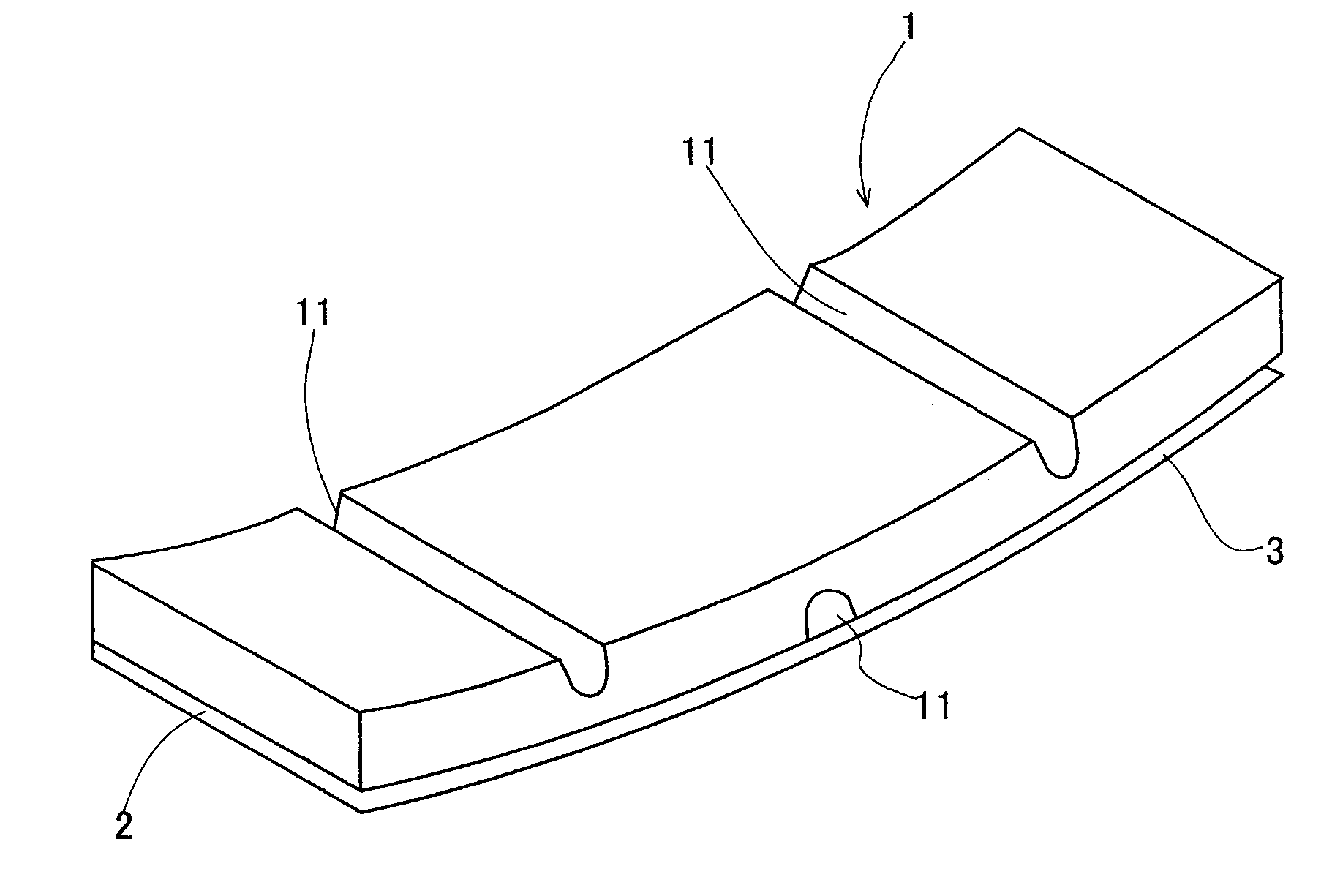
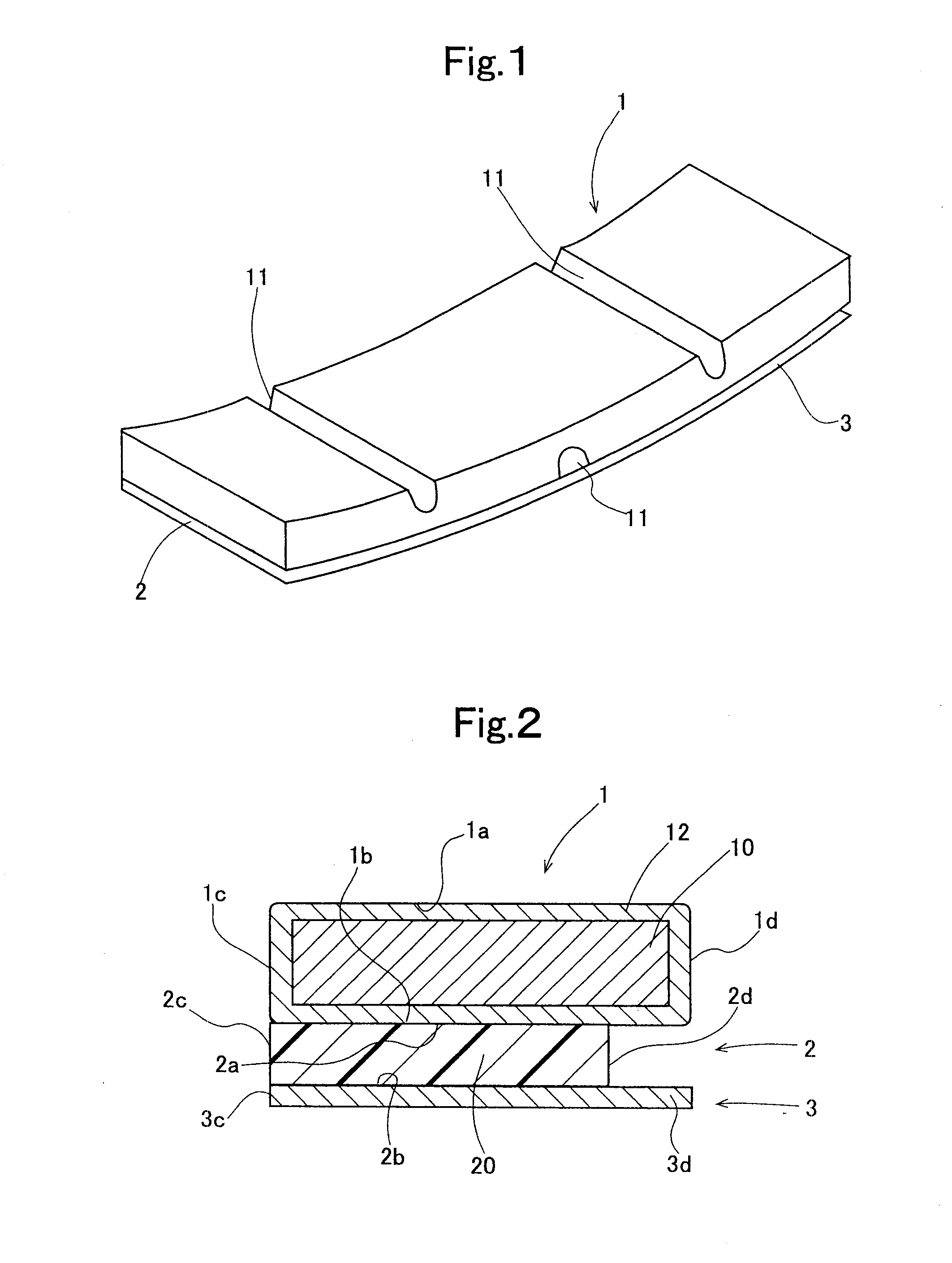
[0073]The present example is a wheel balance weight that is illustrated in FIGS. 1-2. A perspective diagram of the wheel balance weight according to the present example is shown in FIG. 1, and its cross section at the I-I cross section in FIG. 1 is shown in FIG. 2.

[0074]The wheel balance weight according to the present example is constituted of a weight 1, a double-sided adhesive tape 2 and a release coated paper 3.

[0075]The weight 1 is completed by forming a substrate 10 by molding a strip-shaped steel plate whose width is 15-25 mm, thickness is 2-6 mm and a length of 5-200 mm; and by forming a baking-type zinc compound composite film 12 on the surfaces of the substrate 10. This weight 1 is such that grooved portions 11 are disposed in its surface 1a. These grooved portions 11 are formed as a letter “V” shape whose opening width is 0.5-5 mm and depth is 1.9-5.9 mm. And, the weight 1 is curbed so that it becomes like an arc shape in the strip's longitudinal direction. A...

example no.2

Example No. 2

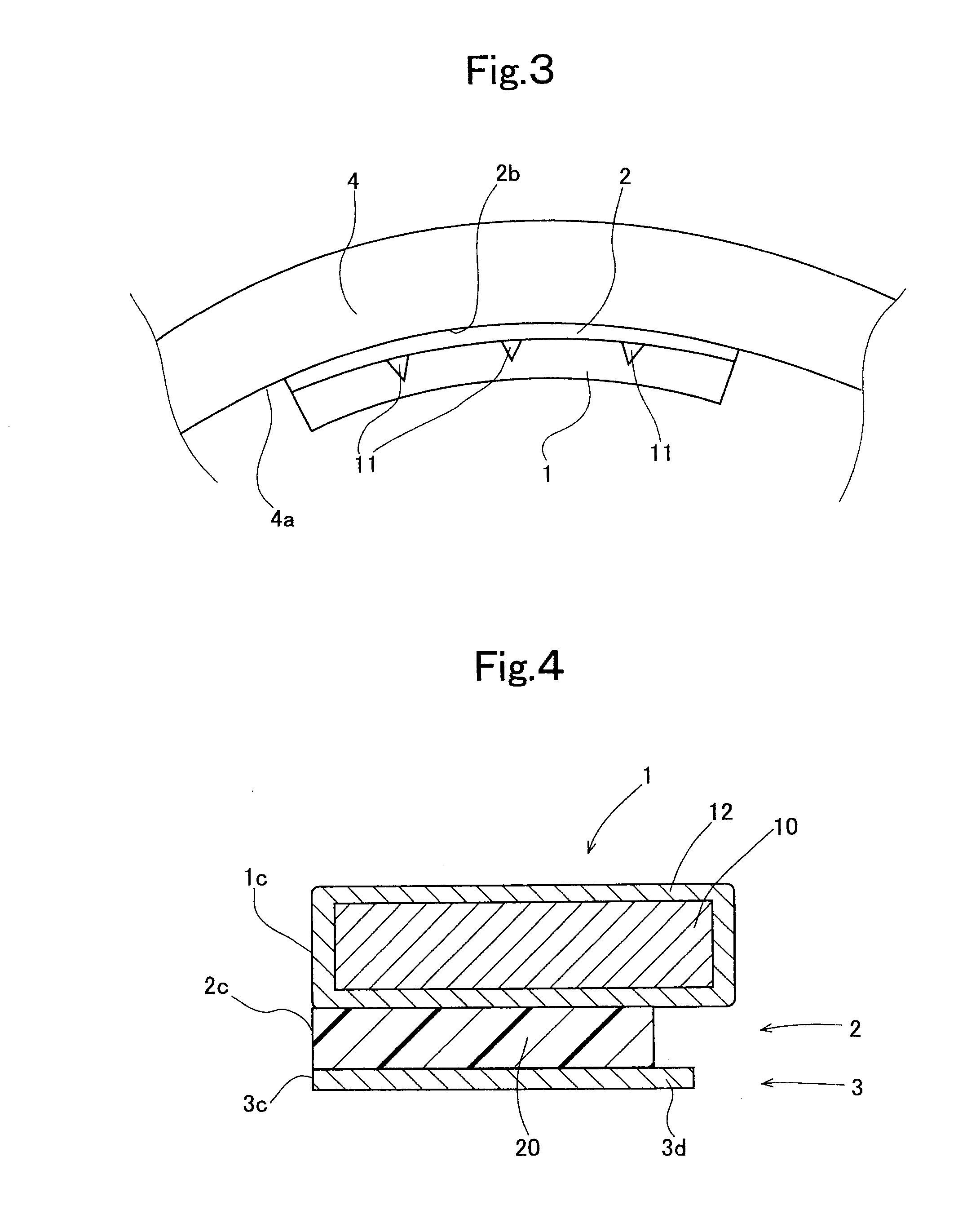
[0085]The present example is a wheel balance weight whose cross-sectional shape is illustrated in FIG. 4.

[0086]The present example is a wheel balance weight with the same construction as that of Example No. 1 except that the width of the release coated paper 3 differs. The release coated paper 3 according to the present example is such that the width is 14-24 mm and is formed shorter than the width of the weight 1 by 0.1-1.0 mm. And, this release coated paper 3 is assembled so that an end 3c coincides with an end 1c of the weight 1 and an end 2c of the double-sided adhesive tape 2.

[0087]In the present example as well, it was possible to simply detach the release coated paper 3 in the same manner as in the case of Example No. 1. That is, in the present example as well, an effect that the workability upon the assemblage improved was demonstrated in the same manner as Example No. 1.

[0088]Moreover, in the wheel balance weight according to the present example as well, it dem...


PUM


Abstract

To provide a wheel balance weight in which a release coated paper is likely to be detached when assembling it with a wheel.A wheel balance weight according to the present invention is such that, in a wheel balance weight including: a substantially-strip-shaped weight; an adhesive-tape portion whose tape front surface is fixed to a weight rear surface; and a release coated paper covering a tape rear surface, it makes the release coated paper likely to be pinched by adjusting the widths of the adhesive-tape portion and release coated paper. Since the wheel balance weight according to the present invention is such that the release coated paper is less likely to be detached before the assembly operation and the release coated paper is likely to be pinched upon assemblage, the handling becomes easy and additionally the workability when assembling the wheel balance weight with a wheel has improved.

Description

CROSS-REFERENCE TO RELATED APPLICATIONS[0001]This application is a division of U.S. application Ser. No. 12 / 158,546 filed Jun. 20, 2008, the entire contents of which is incorporated herein by reference. U.S. application Ser. No. 12 / 158,546 is a National Stage of Application No. PCT / JP06 / 326355 filed Dec. 26, 2006, which claims the benefit of priority from prior Japanese Patent Application No. 2005-379496 filed Dec. 28, 2005.TECHNICAL FIELD[0002]The present invention relates to such a wheel balance weight that the workability upon assembling it with a wheel is high; in particular, it relates to such a wheel balance weight that the release coated paper is likely to be detached when assembling it with a wheel.BACKGROUND ART[0003]In such a wheel-assembled state that a tier of an automobile, or the like, is incorporated into a wheel, there arises a drawback in that, as the imbalance enlarges in the peripheral direction around the rotary shaft of the wheel assembly as well as in the direc...

Claims


Application Information

Patent Timeline
Patent Type & Authority Applications(United States)
IPC IPC(8): F16F15/32
CPCF16F15/328B60B15/28F16F15/32B60B11/08
Inventor TAGUCHI, YUKIYASUSUGAYAUCHI, TATSUHIKOYAMAGUCHI, YUTAKA
Owner TAIHO INDUSTRIES CO LTD
Why Eureka
Try Eureka