Apparatus and method for improving the standby efficiency of a charger, and ultra low standby power charger

Inactive Publication Date: 2011-01-20
RICHPOWER MICROELECTRONICS
View PDF16 Cites 36 Cited by
  • Summary
  • Abstract
  • Description
  • Claims
  • Application Information

AI Technical Summary

Benefits of technology

[0009]According to the present invention, an apparatus for improving the standby efficiency of a charger includes a power monitor circuit connected to two pins of the charger to detect the voltage and the current therefrom, respectively, to generate a control signal. The control signal will disable the charger in a standby mode to reduce the standby power consumption.
[0010]According to the present invention, a method for improving the standby efficiency of a charger includes detection of a voltage and a current from two pins of the charger, and generation of a control signal according to the voltage

Problems solved by technology

However, as the battery 12 is gradually saturated, an upper limit must be set for the increasing battery voltage Vb to control the battery voltage Vb effectively; otherwise, an excessively high battery voltage Vb may damage the battery 12 permanently.
In the standby mode, if electrici

Method used


Image

  • Apparatus and method for improving the standby efficiency of a charger, and ultra low standby power charger
  • Apparatus and method for improving the standby efficiency of a charger, and ultra low standby power charger
  • Apparatus and method for improving the standby efficiency of a charger, and ultra low standby power charger

Examples


Embodiment Construction

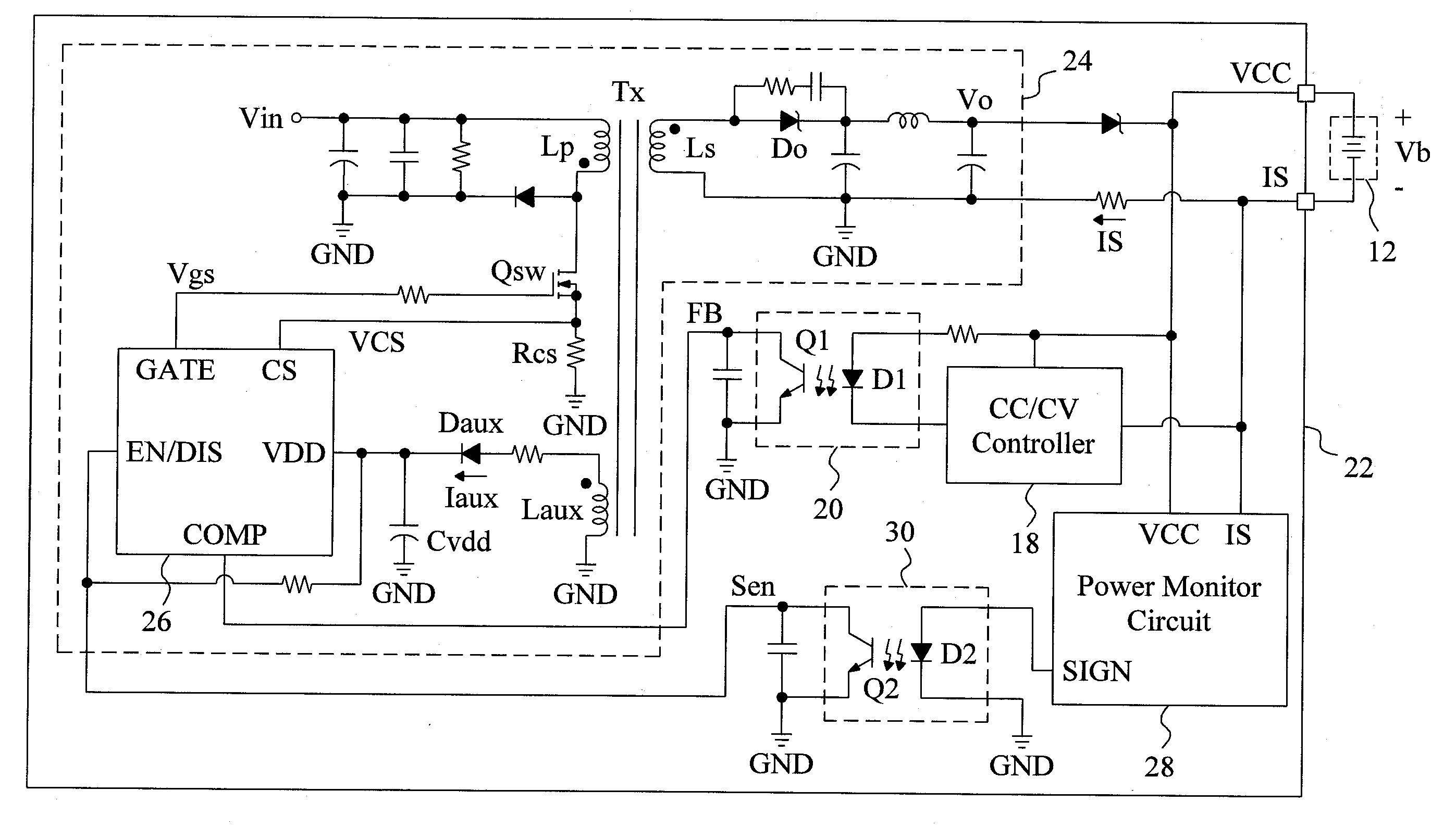
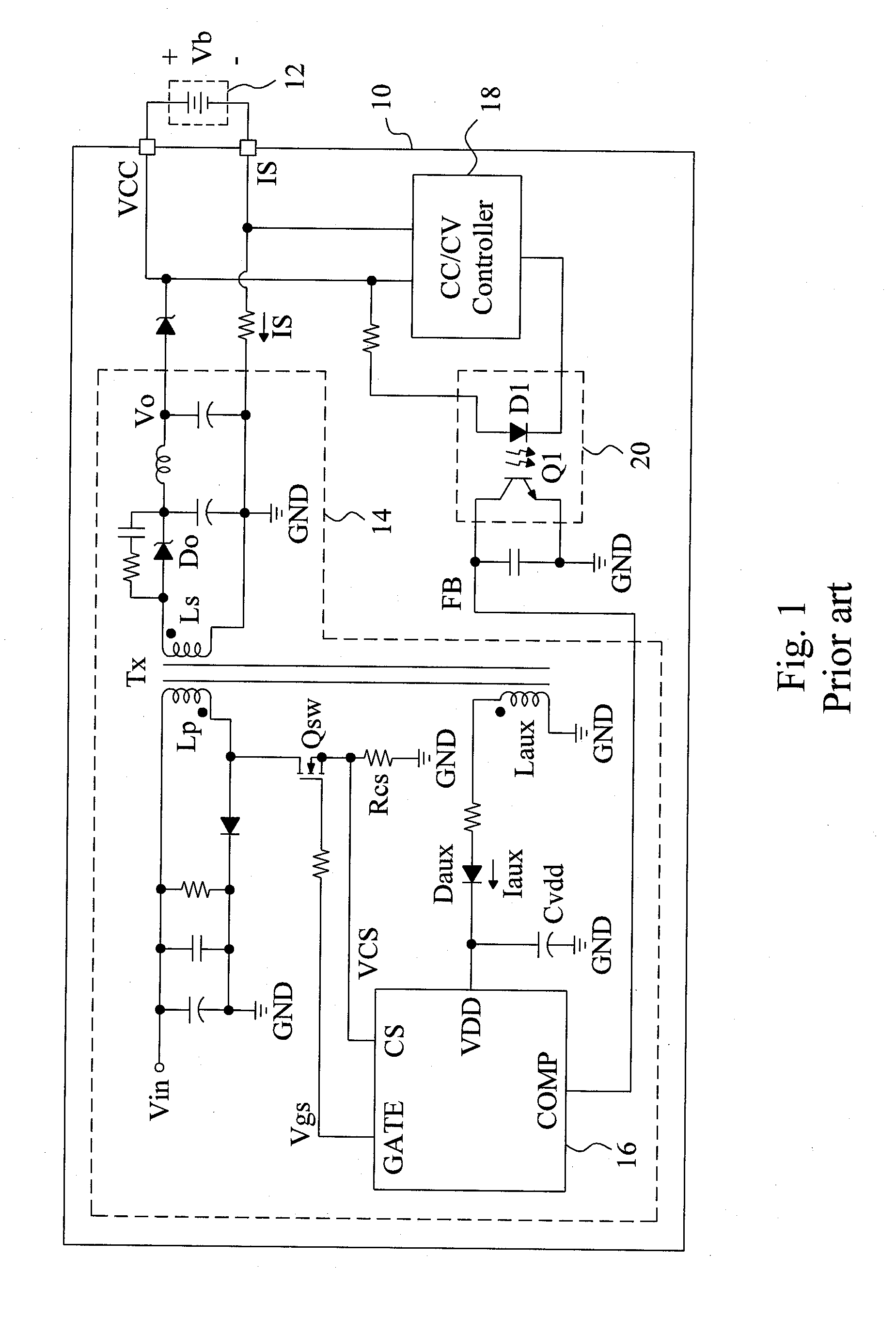
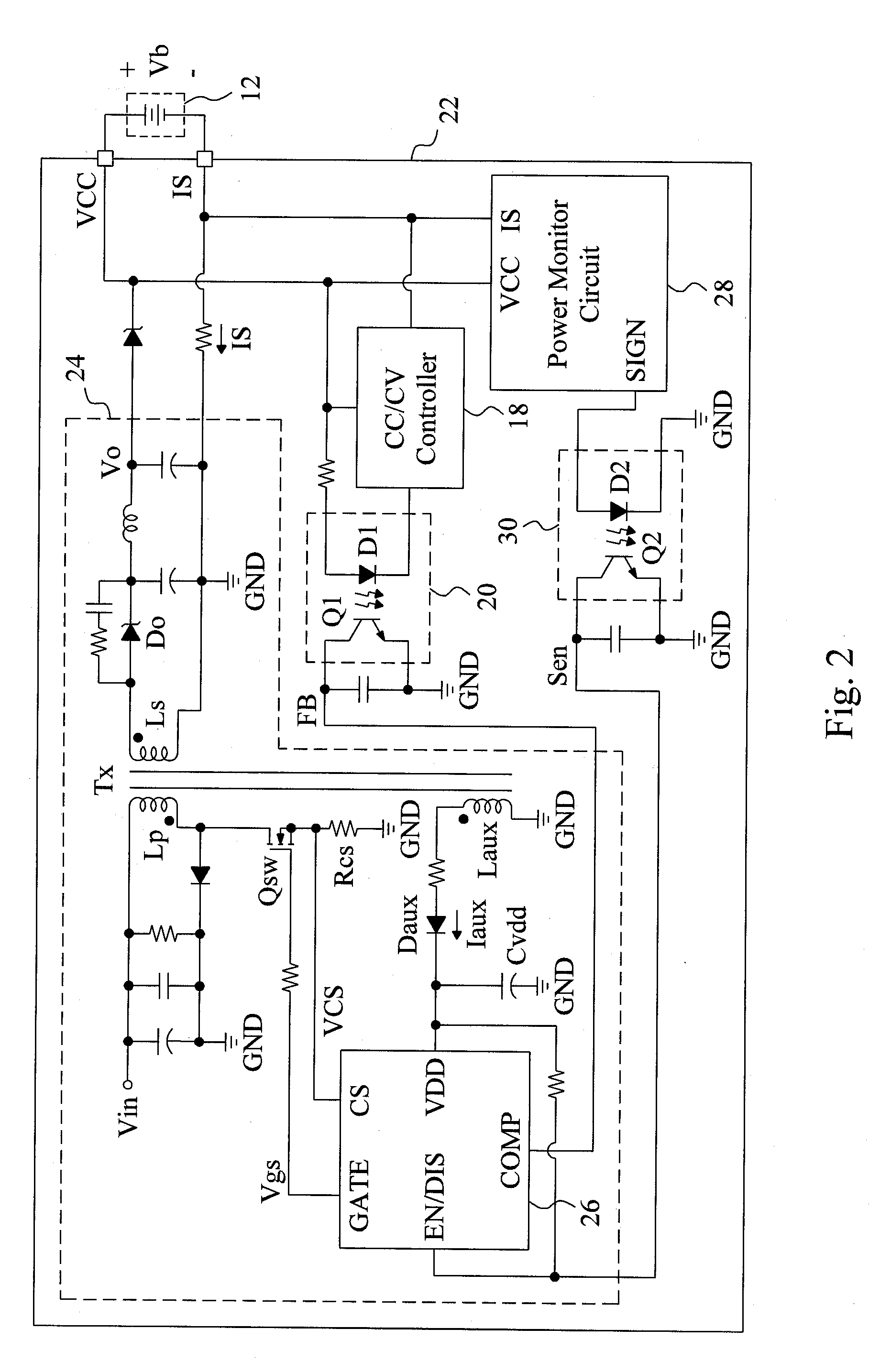
[0017]FIG. 2 is a circuit diagram of an embodiment according to the present invention, in which a charger 22 is similar to the charger 10 of FIG. 1 in that the charger 22 includes two pins VCC and IS for connecting with a battery 12 therebetween, a flyback voltage converter 24 having a power controller 26 to switch a power switch Qsw with a PWM signal Vgs to control the power delivery output from the flyback voltage converter 24, a CC / CV controller 18 for controlling the charger 22 to operate in a constant current mode or a constant voltage mode, and an optical coupler 20 for providing a feedback signal FB applied to a pin COMP of the power controller 26 for the power controller 26 to modulate the duty of the power switch Qsw according to the feedback signal FB and a current sense signal VCS. However, in the charger 22, there are introduced a power monitor circuit 28 connected to the pins VCC and IS for generating a control signal SIGN according to the voltage VCC and the current IS...


PUM


Abstract

A charger has two pins for connecting with a battery therebetween, and an apparatus and method are proposed to determine to wake up or turn off the charger according to a voltage or a current detected from the two pins, to reduce the standby power consumption of the charger.

Description

FIELD OF THE INVENTION[0001]The present invention is related generally to battery chargers and, more particularly, to apparatus and method for improving the standby efficiency of a charger.BACKGROUND OF THE INVENTION[0002]Recently, due to shortage of energy sources and with environmental awareness on the rise, various energy saving functions attract more and more attention in applications of power supplies, of which the standby power consumption is one of the key factors. As shown in FIG. 1, a typical battery charger 10 has two pins VCC and IS for connecting with a battery 12 therebetween, and a flyback voltage converter 14 for charging the battery 12. In the voltage converter 14, a transformer Tx has a primary coil Lp connected between a power input end Vin and a power switch Qsw, and a secondary coil Ls connected between a diode Do and a ground end GND, a power controller 16 provides a pulse width modulation (PWM) signal Vgs from a pin GATE to switch the power switch Qsw and there...

Claims


Application Information

Patent Timeline
IPC IPC(8): H02J7/00
CPCH02J7/0052H02J9/005H02J2007/0059Y02B70/16H02M3/33507H02M2001/0032H02M1/36H02J7/00H02J2207/20H02M1/0032Y02B70/10Y02B70/30Y04S20/20
Inventor LIN, KUN-YULIN, TZU-CHENHUANG, PEI-LUN
Owner RICHPOWER MICROELECTRONICS
Why Eureka
Try Eureka