Rotating log clamp

a technology of log core and clamp, which is applied in the field of clamps, can solve the problems of increasing bias cutting and log core crushing problems, reducing the yield of prior art sawing processes,

Active Publication Date: 2011-02-03
C G BRETTING MFG
View PDF0 Cites 18 Cited by
  • Summary
  • Abstract
  • Description
  • Claims
  • Application Information

AI Technical Summary

Problems solved by technology

Bias cutting and inadequate clamping of the log reduce the yield of prior art sawing processes.
Thus, this cutting process often requires greater force to shear the log than a process involving a blade with teeth, increasing bias cutting and log core crushing problems.
However, these clamps may allow slight movement during the sawing process, especially for logs of large diameter and heavy density.

Method used


Image

  • Rotating log clamp
  • Rotating log clamp
  • Rotating log clamp

Examples


Embodiment Construction

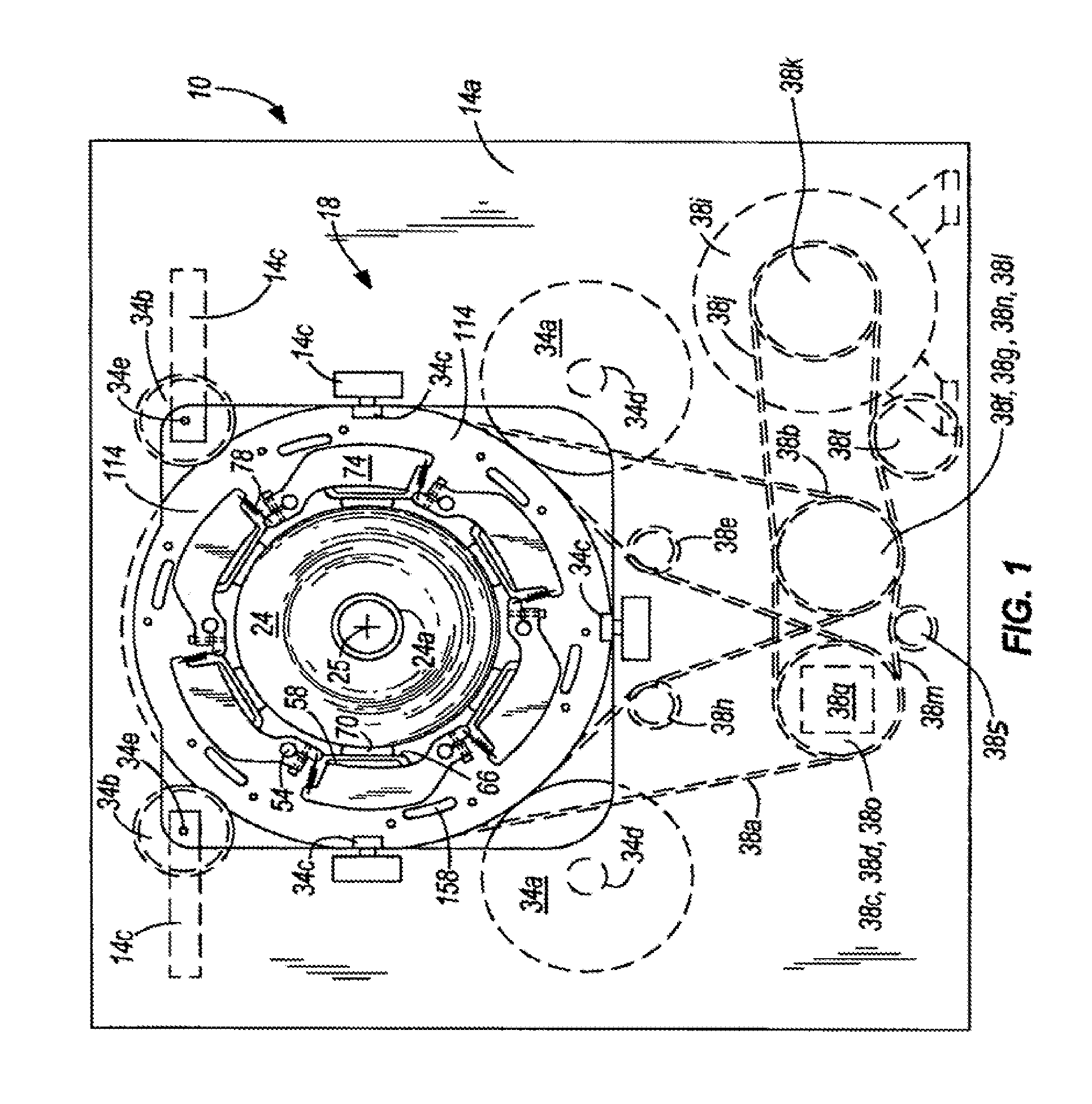
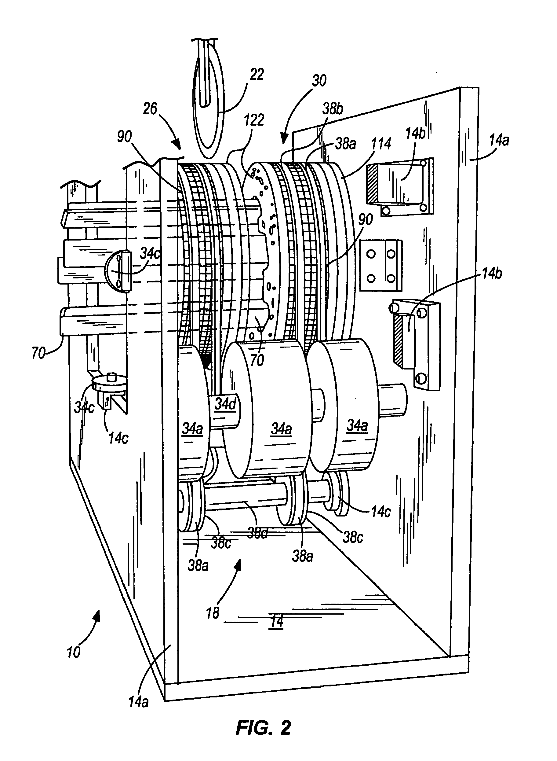
[0024]Referring to the figures, and more particularly to FIGS. 1, 2, and 3, a log saw assembly 10 constructed in accordance with an exemplary embodiment of the present invention is illustrated. Although the embodiments of the present invention described below and illustrated in the figures are presented with reference to the log saw assembly 10, it should be noted that the present invention can also be employed in other types of equipment that require clamping operations, whether those operations include sawing or not.

[0025]The log saw assembly 10 includes a frame 14, a log saw clamping assembly 18, and a log saw having a log saw blade 22 (schematically illustrated in FIGS. 2 and 3). In some embodiments, as discussed further below, multiple log saw assemblies 10 are utilized in combination. Additionally, other components generally known in the art can he utilized with the log saw assembly 10. In some embodiments, a log pusher is utilized to longitudinally locate a product roll or lo...


PUM

PropertyMeasurementUnit
radial thicknessaaaaaaaaaa
diameteraaaaaaaaaa
diameteraaaaaaaaaa

Abstract

A rotating saw clamp for clamping a product roll to be sawn. The rotating log saw clamp includes a first portion disposed for rotation about an axis and a second portion disposed for rotation with the first portion and movable relative to the first portion between an open position and a clamping position. The second portion is rotatable from the clamping position to the open position in rotation of the first and second rotating portions in a common direction.

Description

BACKGROUND OF THE INVENTION[0001]The invention generally relates to clamps. More particularly, the invention relates to clamps for securing rolls of paper (commonly referred to in the trade as “logs”) during sawing processes.[0002]Many types of paper are produced in logs for ease of manufacture. As used herein and in the appended claims, the term “log” is meant to include rolls of paper products such as napkins, paper towels, facial tissue, toilet tissue, newsprint, and the like. Also, because the present invention is not limited to rolls of paper products, the term “log” is meant to include rolls of products which are made from other materials including without limitation cellophane, plastic sheeting, and other synthetic materials, fabric, woven, and non-woven textiles and cloth, foil, etc., regardless of product porosity, density, and dimensions. These logs must typically be sawn into shorter rolls more readily used by consumers. Automating the sawing process is necessary to achie...

Claims


Application Information

Patent Timeline
Patent Type & Authority Applications(United States)
IPC IPC(8): B26D7/04B26D3/16B26D7/02
CPCB26D3/16B26D7/02B26D2007/013Y10T279/18Y10T279/17717Y10T279/17231Y10T29/49998Y10T279/182Y10T83/7487Y10T83/7533Y10T83/7573Y10T83/758
Inventor RUNDELL, WAYNE G.LUMBERG, ERIC J.STACKLEY, MARK A.
Owner C G BRETTING MFG
Why Eureka
Try Eureka