Camera unit and sensing device

a technology of sensing device and camera, which is applied in the field of camera unit and sensing device, can solve the problems of affecting the in-vehicle camera, the normal operation of the in-vehicle camera, and the noise generated by the radio unit, and achieves good shielding performance of electromagnetic waves, high resistance to electrostatic discharge, and low cost

Active Publication Date: 2011-02-03
RICOH KK
View PDF5 Cites 131 Cited by
  • Summary
  • Abstract
  • Description
  • Claims
  • Application Information

AI Technical Summary

Benefits of technology

The present invention provides a camera unit that is resistant to electrostatic discharge and good at shielding electromagnetic waves at a low cost.

Problems solved by technology

The technical problem addressed in this patent is to provide an in-vehicle camera that has high resistance to electrostatic discharge and high waterproofing performance, while also eliminating the influence of electromagnetic waves and protecting the camera from damage caused by external factors such as electrostatic discharge and radiation sources. Additionally, the in-vehicle camera needs to have a high resistance to electrostatic discharge while still ensuring adequate EMI measures.

Method used


Image

  • Camera unit and sensing device
  • Camera unit and sensing device
  • Camera unit and sensing device

Examples


Embodiment Construction

[0056]A description will be given of embodiments of the present disclosure with reference to the accompanying drawings.

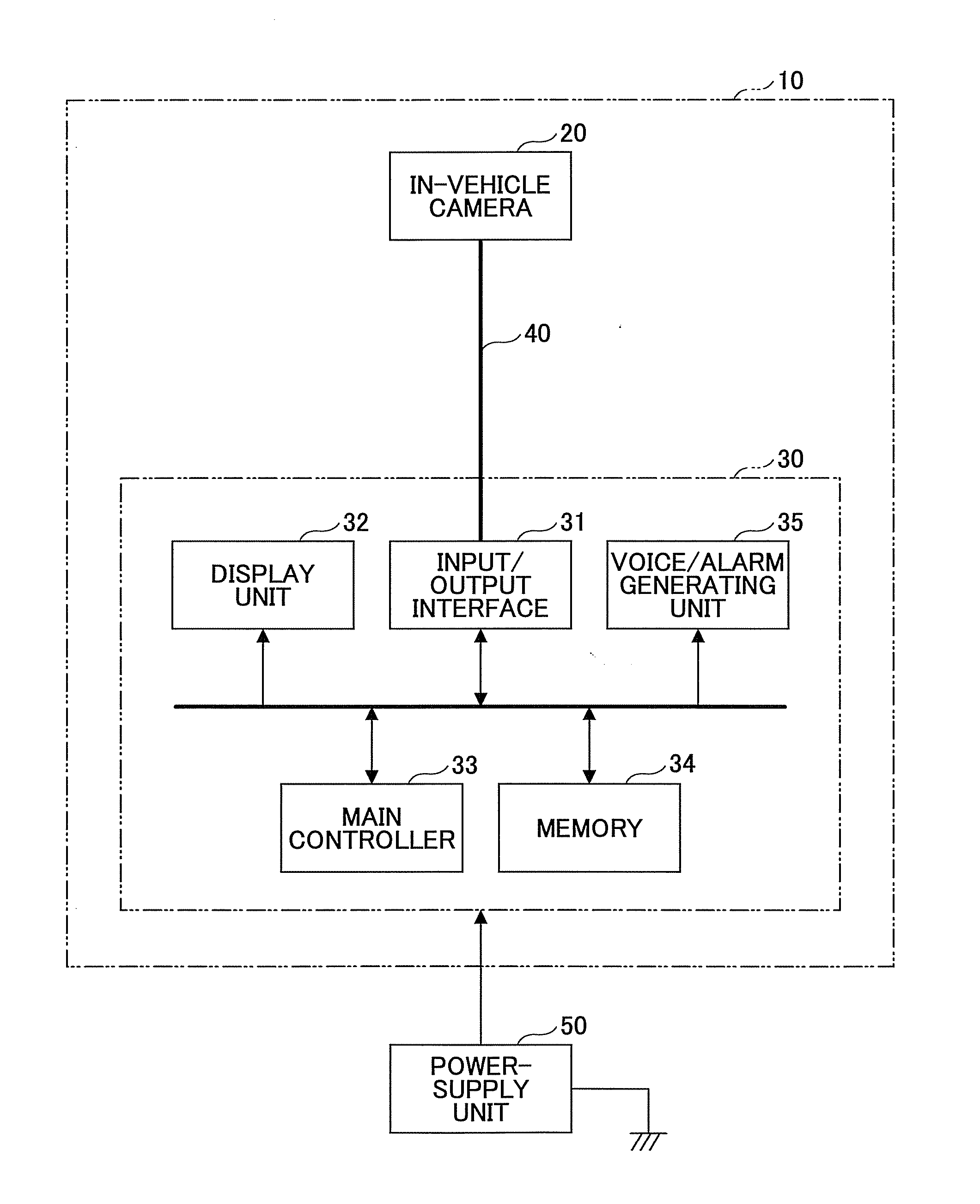
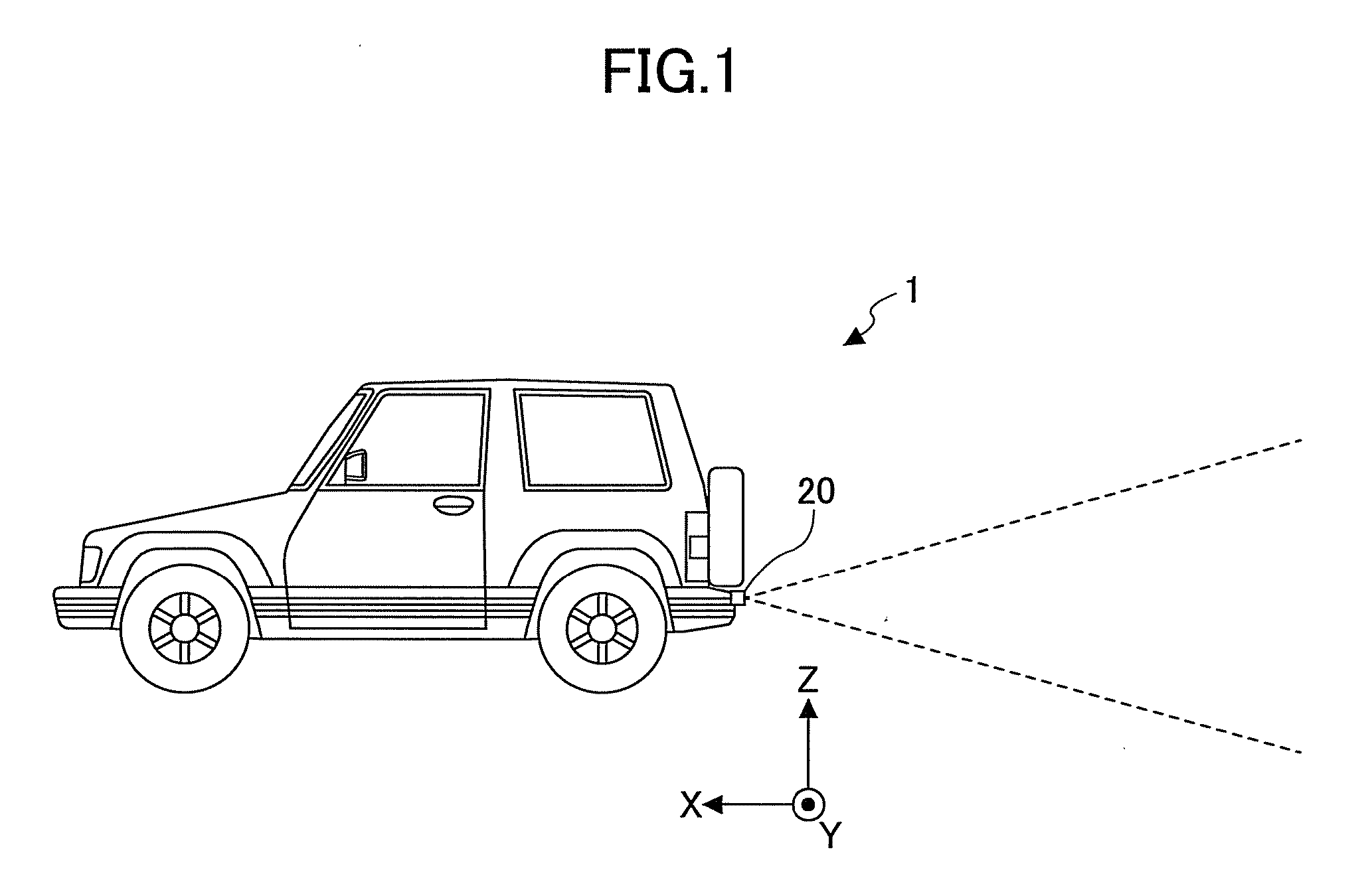
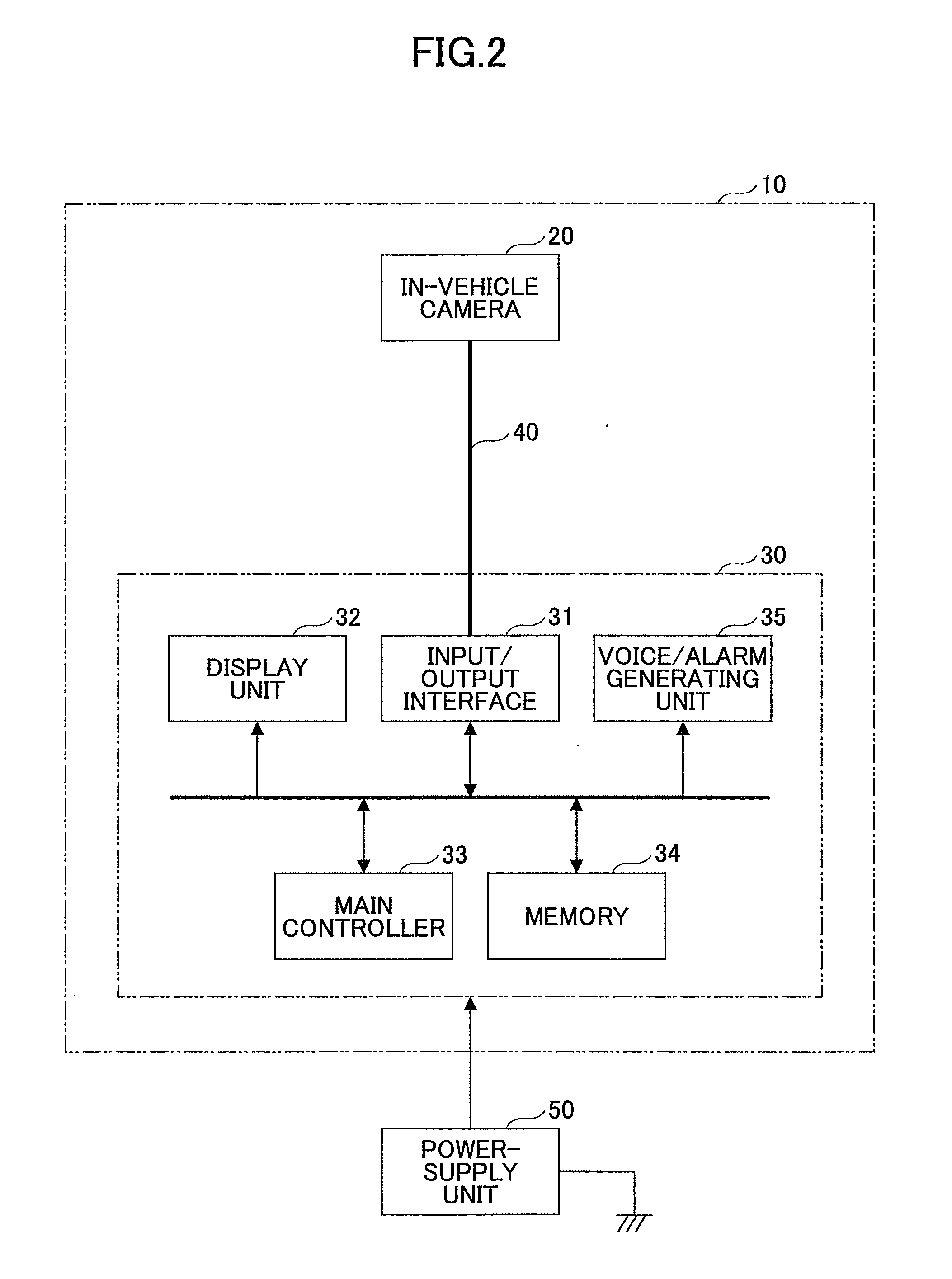
[0057]FIG. 1 illustrates the composition of a vehicle 1 in which an in-vehicle camera 20 is arranged.

[0058]For the purpose of assisting a driver's vision, an in-vehicle camera is installed at a rear portion, a front portion or a side portion of a vehicle, so that an image indicating the surroundings of the vehicle captured by the camera is displayed on a display unit, such as a liquid crystal display monitor, in the vehicle. In order to provide a safe system without a dead angle, it is required that the in-vehicle camera has a large viewing angle. In view of a vehicle design, it is desired that the in-vehicle camera is not conspicuous. Hence, it is also required that the in-vehicle camera is of small size.

[0059]A back-monitor type camera which is a popular in-vehicle camera is externally attached to the vehicle, and it is required that the camera has a high waterpro...


PUM


Abstract

A camera unit includes an image sensor, a circuit board in which a signal processor circuit to process an output signal of the image sensor is formed, a cable including a signal conductor element and a ground conductor element and connected at one end to the circuit board, and a shielding component formed to enclose the circuit board therewith. The ground conductor element is connected to both a ground terminal of the circuit board and the shielding component in a vicinity of the end of the cable.

Description


Claims


Application Information

Patent Timeline
Owner RICOH KK
Why Eureka
Try Eureka