

Drive device
a technology of drive device and drive shaft, which is applied in the direction of magnetic circuit rotating parts, electric propulsion mounting, magnetic circuit shape/form/construction, etc., can solve the problems of heat-resistant temperature disadvantage and heat-resistant temperature disadvantage, and achieve excellent thermal shielding properties and less flow rate of refrigeran
- Summary
- Abstract
- Description
- Claims
- Application Information
AI Technical Summary
Benefits of technology
Problems solved by technology
Method used
Image

Examples
first embodiment
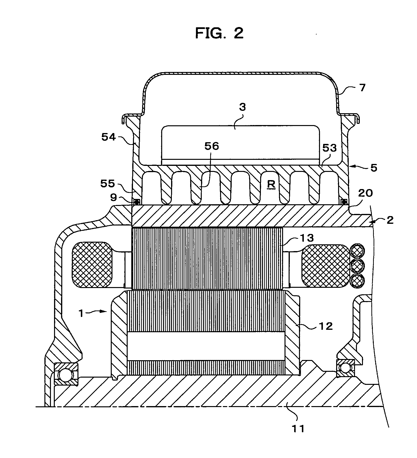
[0040] Subsequently, FIGS. 2 and 3 show, in a simplified manner, a longitudinal, cross section, in an axial direction, and a side (partially sectioned) as viewed from an axial end, of the drive unit according to a In FIG. 2, the reference numeral 1 denotes an electric motor, 11 a rotor shaft of the motor, 12 a rotor core, and 13 a stator core, and in FIG. 3, a circle shown by a broken line indicates an outside diameter of the electric motor 1, a circle shown by an alternate long and short dash line and having a maximum diameter indicates an intermeshing pitch diameter of a ring gear of the differential device, and respective circles shown by alternate long and short dash lines and having a minimum diameter and a medium diameter indicate intermeshing pitch diameters of respective gears of the counter gear mechanism that transmits power between the rotor shaft 11 and the ring gears of the differential device.
[0041] In this embodiment, an inverter 3 is received in an inverter casing 5...
eighth embodiment
[0064] A fin arrangement and a refrigerant flow that are adoptable in this embodiment can be made the same as those described in the eighth embodiment with reference to FIGS. 14 and 15 in the case where the third chamber R3 is a simple space. Also, in the case where the third chamber R3 is to be also communicated to the refrigerant flow passages, all the respective chambers may be connected in parallel to the flow passages as inferred from the parallel connection described with reference to FIG. 14, and connection in series may be provided in view of temperature gradient so as to allow the refrigerant to flow through the first chamber R1, the second chamber R2, and the third chamber R3 in this order, as inferred from the connection in series described with reference to FIG. 15.
tenth embodiment
[0065] Finally, a tenth embodiment shown in FIG. 17 assumes, unlike the respective embodiments described above, the case where an inverter 3 is united with a heat sink 33, or a substrate itself of an inverter 3 is constituted as an inverter module that constitutes a heat sink 33. In this embodiment, the inverter 3 together with the heat sink 33 that is united with a substrate thereof are received and fixed in an inverter casing 5 composed of a separate member from the inverter. And, since the heat sink 33 and the inverter casing 5 are separate from each other, appropriate sealing means, illustration of which is omitted, seals between them.
[0066] While the invention has been described above in detail on the basis of ten embodiments, it is not limited to such embodiments but can be embodied with its concrete construction modified variously within the scope described in the claims. For example, the low thermal conductive member 6 except that in the eighth embodiment is assumed to compr...
PUM
 Abstract
Description
Claims
Application Information