Valve with swirling coolant

a valve and coolant technology, applied in the direction of functional valve types, turbine/propulsion fuel valves, machines/engines, etc., can solve the problems of hard on the fuel control components of the turbine fuel system, liquid fuel system remains inoperable, and coking can still be a problem, so as to achieve more consistent operation and reduce coking

Active Publication Date: 2009-05-05
JANSENS AIRCRAFT SYST CONTROLS
View PDF26 Cites 16 Cited by
  • Summary
  • Abstract
  • Description
  • Claims
  • Application Information

AI Technical Summary

Benefits of technology

[0012]The present invention provides liquid fuel valves for use in the extreme temperature and pressure conditions of land and air based gas turbine engine applications. The compact valve package is cooled by a dedicated liquid coolant circuit circulating relatively low temperature water past critical parts of the valve to provide more consistent operation and reduce coking.
[0014]Dedicated water supply and return ports are used to connect the valve to a water supply via suitable lines. Preferably, the water return and supply ports are tangential to the valve chamber so that a swirling motions is effected inside the valve which aids in distributing the coolant along the interior of the valve and thereby improves heat transfer.
[0018]Thus, in one aspect the present invention provides a water cooled liquid fuel check valve. The check valve can have a water jacket, having tangential water supply and return ports, that fits over a valve body having a spring biased fuel actuated valve member biased to close off communication between the fuel inlet and outlet ports. The valve body has an annular groove forming the cooling water circuit between the valve body and the water jacket in communication with the water supply and return ports. The valve can also have a special baffle member with a series of openings, some of which are axially aligned with the poppet valve member allowing liquid fuel to flow into a primary metering chamber. The baffle member also has radial openings to a stem with an axial passageway leading a portion of the fuel to a Helmhotz type resonance chamber, which preferably is defined by the interior of the poppet, to dampen pressure oscillations in the exiting fuel flow.
[0020]In yet another aspect, the present invention provides a liquid fuel metering valve with a dedicated fluid coolant circuit and purge air and / or distributor sections. The valve includes three isolated flow circuits, namely a liquid fuel circuit, a cooling fluid circuit and a purge air circuit. In particular, the liquid fuel circuit includes a fuel inlet port, a fuel only section of the valve chamber and an outlet port. The purge air circuit includes an air inlet port, an air only section of the valve chamber and the outlet port. The cooling fluid circuit includes cooling fluid supply and return ports for circulating cooling fluid of proximate the valve member. The coolant circuit is preferably entirely separate passageways, for example having a spiral or helical section between the valve body and a water jacket. However in a preferred 3-way metering / purge valve construction, the fuel and purge air circuits, preferably share one or more passageways and the outlet port leading to the combustor(s) while the valve member isolates the air flow form the fuel flow so that these streams do not mix. The valve thus can be operated to meter fuel to the burner nozzle during sustained liquid fuel operation and alternatively to purge the downstream fuel lines and burners with air to cool them and extricate residual liquid fuel to prevent coking during shut down and gaseous fuel operation of the turbine.
[0021]In still another aspect, the valve is a fluid cooled combined purge air and distributor valve. In this case, the housing defines the aforementioned three flow circuits as well as a distributor section having a plurality of outlet ports which make up part of the liquid fuel circuit. Also, the liquid fuel circuit preferably includes a plurality of flow orifices disposed within the liquid fuel circuit between the fluid inlet port and an associated one of the plurality of outlet ports. At least one of the flow orifices receives a module that mounts to the valve housing. Each module can define a flow passageway or a plug blocking the flow of liquid fuel through the associated flow orifice. The valve is arranged so that the liquid fuel inlet port is in communication with the plurality of flow orifices when the valve member is in a first, lesser open position and in communication with the plurality of flow orifices and the plurality of outlet ports when the valve member is in a second, fully open position. This arrangement provides at least two benefits. First, it provides for a lesser volume of liquid fuel to flow to the turbine atomizer and burners, for example during light-off. Second, the modules allow the valve to be configured to flow liquid fuel to one or sub-set of burner nozzles designated to begin combustion at light-off.

Problems solved by technology

This extreme environment is very hard on the fuel control components of the turbine fuel system, particularly for dual fuel turbines in which the during sustained gaseous burn, the liquid fuel system remains inoperable for long periods of time.
Even with good air purging, coking can still be a problem.
Not all of the components in the fuel system subjected to high temperatures, for example fuel check and cut-off valves, are often not able to be purged because they may be providing the barrier between the fuel and air streams.
Moreover, since the air purge control valves may themselves be located at or near the combustion cans, they too are subject to the adverse affects of coking.
However, this system requires a heat exchanger and either a separate fuel recirculation pump or increased duty on the main fuel pump.

Method used


Image

  • Valve with swirling coolant
  • Valve with swirling coolant
  • Valve with swirling coolant

Examples


Embodiment Construction

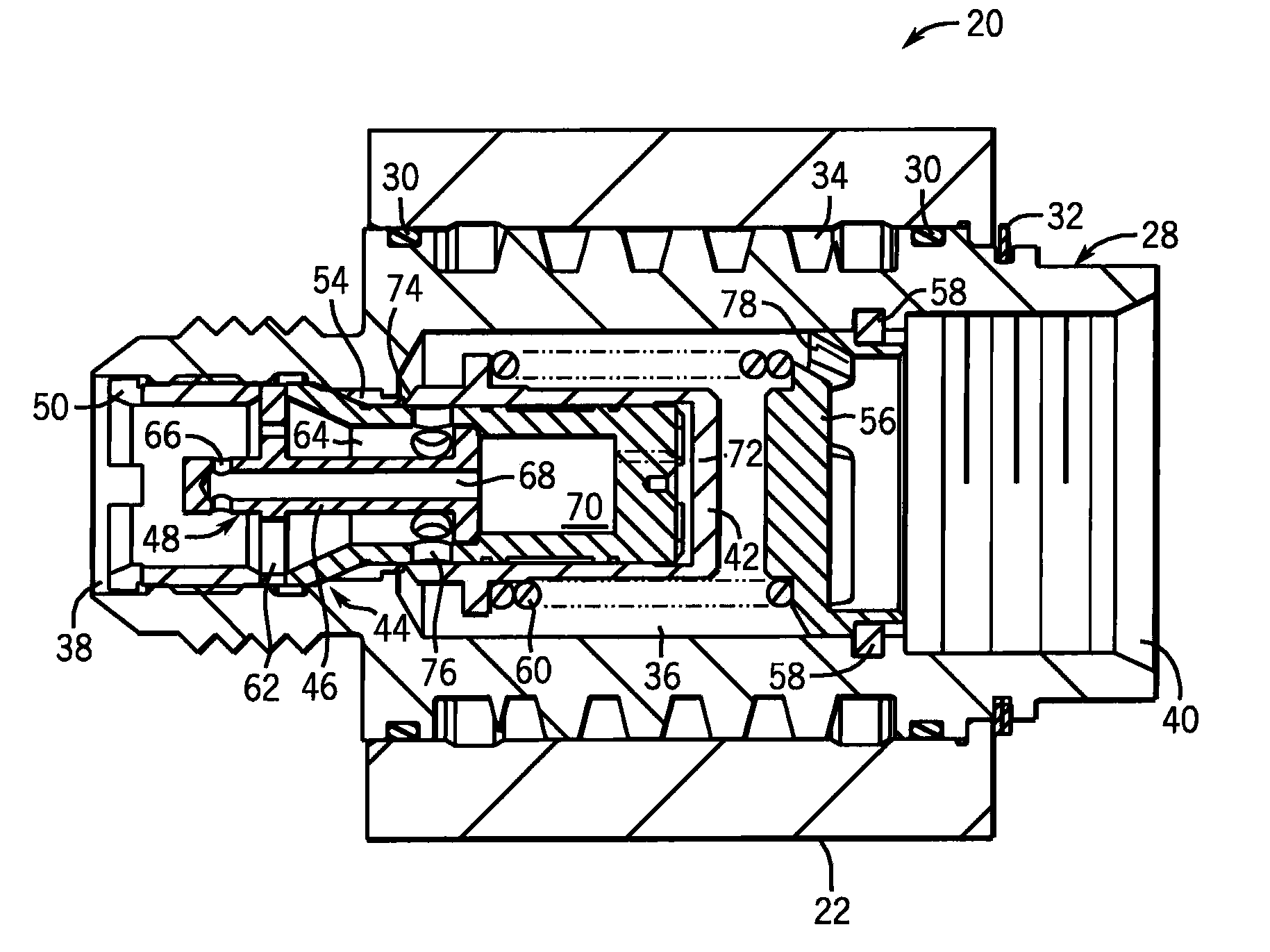
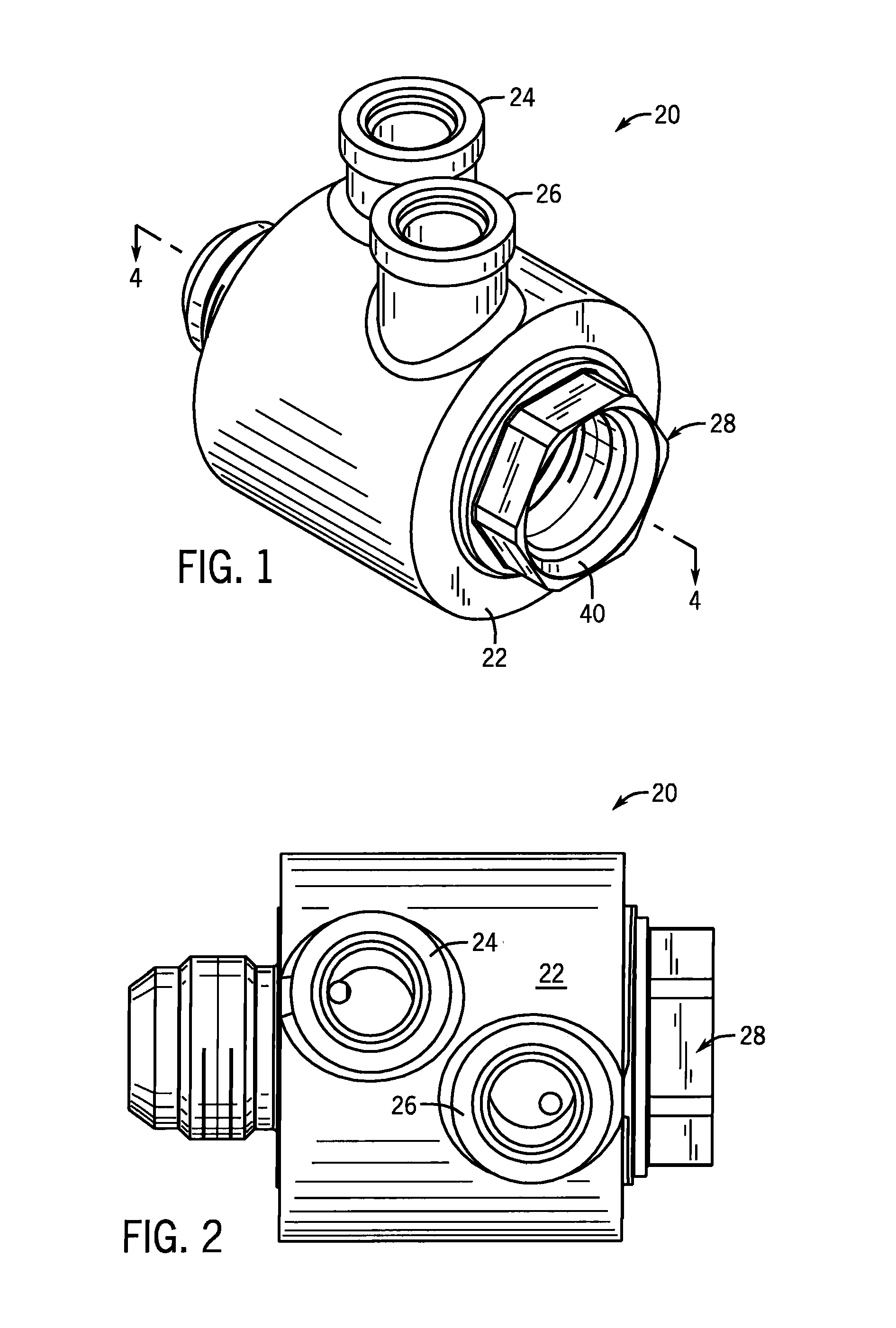
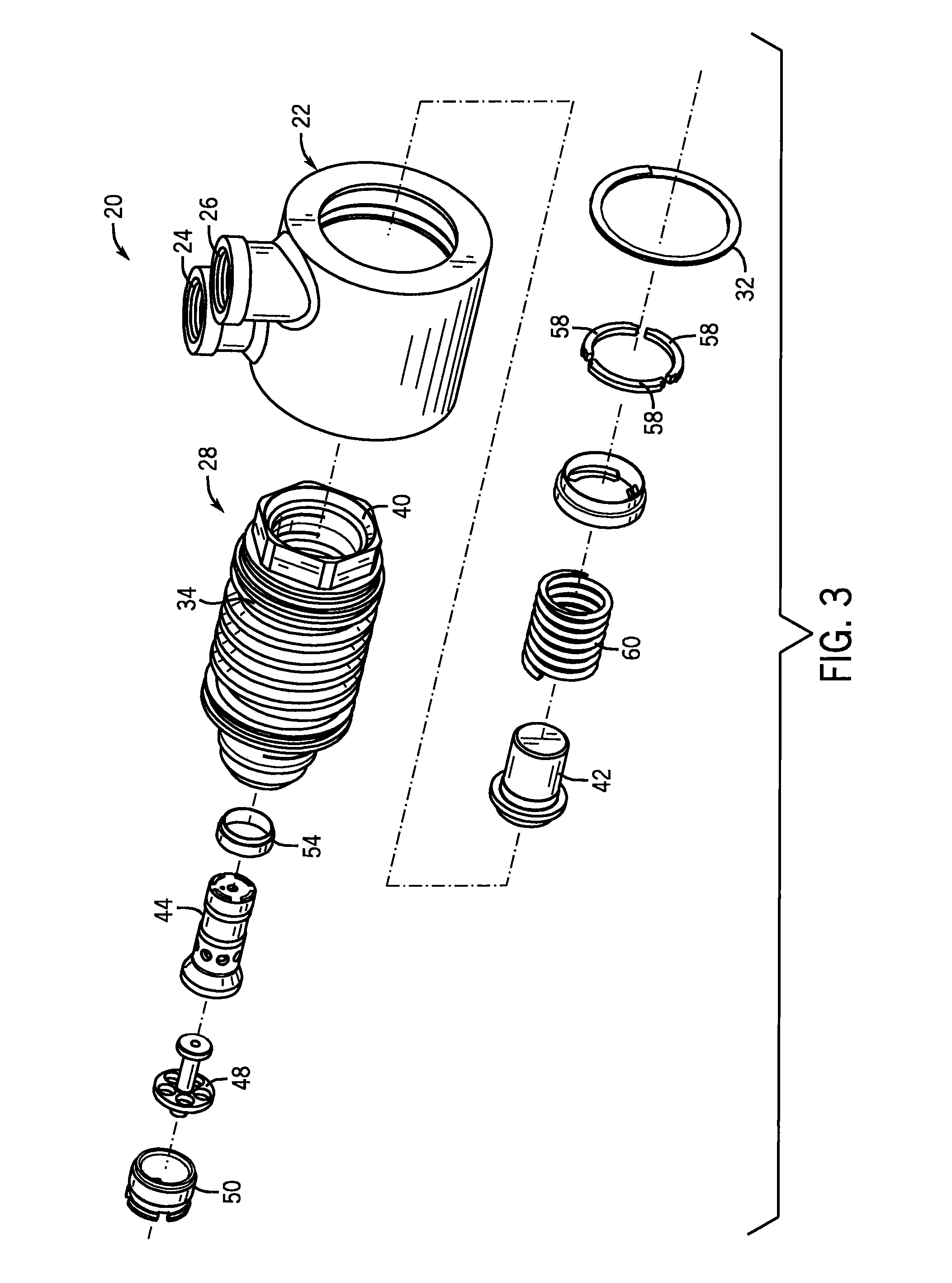
[0033]The present invention provides a non-fuel liquid cooled liquid fuel valve for use in the extreme temperature and pressure environment of the fuel system of an air or ground gas turbine engine. The valve can take the form of a check valve, an air purge valve, a distributor valve, a combination air purge and distributor valve and the like. In any form, a movable valve member controls the flow of liquid fuel through the valve's fuel circuit and a separate cooling circuit circulates coolant through the valve near or alongside the valve member. Although not shown, for each embodiment of the valve suitable lines or conduit couple the valve to a water supply, which can be continuous cool water supply or a recirculated supply tank with or without external cooling. The coolant is any suitable non-fuel fluid, preferably water and preferably of a lower temperature than the liquid fuel. For simplicity, the following valve embodiments will be described as being water cooled.

[0034]FIGS. 1-5...


PUM


Abstract

A water cooled valve is provided in the form of a check valve, an air purge valve, a distributor valve, a combination air purge and distributor valve and the like for use in the liquid fuel system of a gas turbine. A movable valve member controls the flow of fluid through the valve's fuel circuit. A separate cooling circuit circulates cooling water through the valve near or alongside the valve member. The water is of a lower temperature than the high temperature liquid fuel, and thereby carries away heat transferred to the valve by the fuel. In one form, the cooling circuit is formed in part by a helical groove in the periphery the valve body housing the valve member. A sealed water jacket surrounds the valve body and has dedicated supply and return ports for coupling the valve to a water supply via water lines. The water ports are positioned tangentially to induce swirling flow inside the valve.

Description

CROSS-REFERENCE TO RELATED APPLICATION[0001]This application is a continuation-in-part of U.S. application Ser. No. 10 / 462,295, filed Jun. 16, 2003, now U.S. Pat. No. 6,931,831 which claims benefit to U.S. provisional application Ser. No. 60 / 389,827, filed Jun. 18, 2002, and this application also claims benefit to U.S. provisional application Ser. No. 60 / 501,250 filed Sep. 9, 2003.STATEMENT OF FEDERALLY SPONSORED RESEARCH OR DEVELOPMENT[0002]Not applicable.BACKGROUND OF THE INVENTION[0003]1. Technical Field[0004]The present invention relates to fuel delivery systems for land and air based gas turbine engines, and in particular to liquid fuel control valves for turbine engines.[0005]2. Description of the Related Art[0006]Gas turbine engines have a set of rotating turbine blades that compress air leading to a combustion chamber into which fuel is injected and ignited. Fuel is delivered through metering orifices to burners in the combustion chamber under pressure through a fuel line. C...

Claims


Application Information

Patent Timeline
Patent Type & Authority Patents(United States)
IPC IPC(8): F16K49/00F01D25/12F02C7/232F02M37/18
CPCF01D25/12F02C7/232F02M37/18F16K49/005F05D2260/602F05D2260/232Y10T137/6579Y10T137/7929
Inventor JANSEN, HARVEY B.
Owner JANSENS AIRCRAFT SYST CONTROLS
Why Eureka
Try Eureka