Control device for medical catheters

a control device and catheter technology, applied in the field of medical catheter control, can solve the problems of affecting the accuracy or control of the medical practitioner, the inability of the medical practitioner to achieve the inability to accurately or control the necessary force for the deployment of the stent-graft, so as to achieve the effect of reducing the cost of manufacturing, reducing the risk of stent insertion, and reducing the risk of insertion

Inactive Publication Date: 2010-11-23
ANSON MEDICAL LTD
View PDF11 Cites 75 Cited by
  • Summary
  • Abstract
  • Description
  • Claims
  • Application Information

AI Technical Summary

Benefits of technology

[0007]The present invention performs similar functions to the AneuRx system but employs fewer components, allowing it to be fabricated more cheaply, operated more simply and for the mechanism to have greater reliability.
[0010]A preferred feature of the present invention is a modification to the first or second threaded component. The modification allows the diameter of the threaded component to be increased if it is an outer thread, or to be decreased if it is an internal thread, beyond a point where the first threaded component no longer engages the second threaded component. The modification allows the rotatable barrel to have two modes of operation: the first operating mode occurs when the first and second threaded components are engaged, the barrel is rotated and operates the lead screw to provide mechanical advantage and a slow controlled release. The second operating mode occurs when the first and second threaded components have been adjusted so that they cannot engage and the rotatable barrel can be slid axially, without mechanical advantage but at higher speed. The first operating mode is optimum for releasing the implant while the second operating mode is more suitable for returning the sheath to its starting position, or for deploying a second, less critical component of the implant.
[0012]A further improvement in the basic system can be achieved if the modified threaded component is stable in both the engaged or disengaged states. This allows the mechanism to employ the mechanical advantage of the lead-screw, but once disengaged to return over the threaded part as a simple sliding movement. This feature allows the rapid return of the sheath to the starting position.
[0015]In a practical embodiment of the invention, the handle of the catheter system is threaded over part of its surface with a multi-start thread. A rotatable barrel with a smooth inner surface is free to slide over the threaded handle. The barrel is provided with a number of short cylindrical pins which are radially arranged to pass through the wall of the barrel. Preferably, where a multi-start thread is employed, at least one radially arranged pin is employed to engage with each separate thread. The pins can slide in the wall of the barrel and their length is arranged such that when in a first position, they project maximally into the barrel and the pins engage the thread of the handle. Thus the pins form the first threaded component referred to above and the threaded handle comprises the second threaded component. In a second position, the pins can be pushed outwards through the wall of the barrel so that they no longer engage the thread of the handle, allowing the barrel to move freely over the threaded handle.
[0017]Conveniently, the pins can be moved from the said first position to the said second position by decreasing the depth of the thread cut into the handle or by providing a raised component over which the pins are made to pass. Advantageously, the diameter of the pins is increased at one end, said end lying inside the rotatable barrel. This feature prevents the pin from falling out of the barrel, while the length of the pin is such that the body of the handle passing through the rotatable barrel will prevent the pin from falling through the wall of the barrel into the handle.

Problems solved by technology

The first is that the highly compressed implant pushes against the wall of the sheath with such force that withdrawing the sheath also requires a considerable force.
A second (allied) problem is that providing the necessary force to deploy the stent-graft can be difficult for the medical practitioner to achieve with accuracy or control, allowing the implant to be deployed too quickly and, potentially, displaced from its intended landing site.
Additional complexity is added in this system because the sheath stretches significantly while it is being withdrawn.
When the medical practitioner's hand is being repositioned on the barrel of the handle, the barrel is free to rotate and is prone to spin back as the sheath springs back to its original length.
Introduction of the ratchet incurs a further complexity.

Method used


Image

  • Control device for medical catheters
  • Control device for medical catheters
  • Control device for medical catheters

Examples


Embodiment Construction

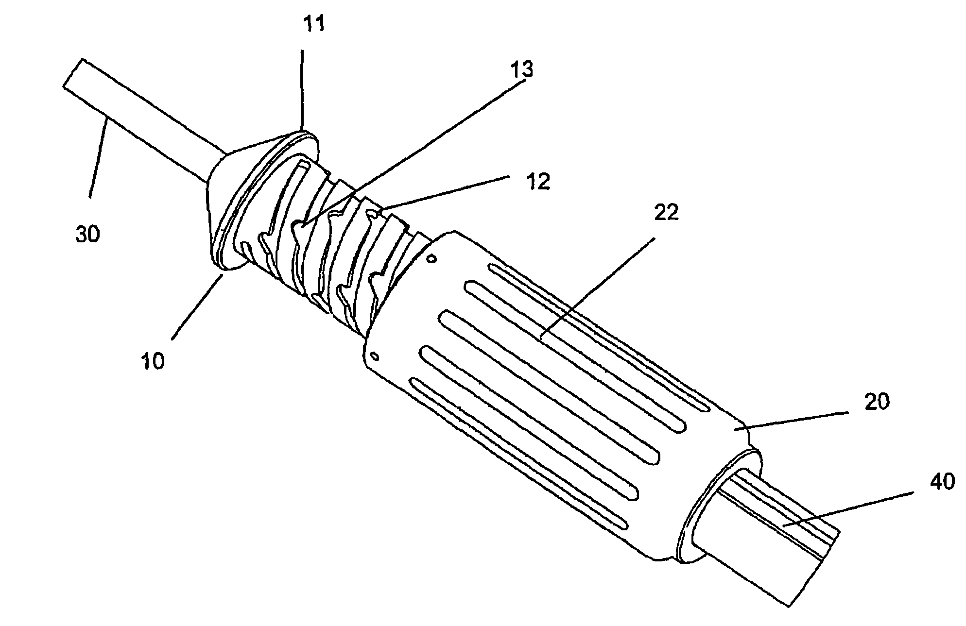
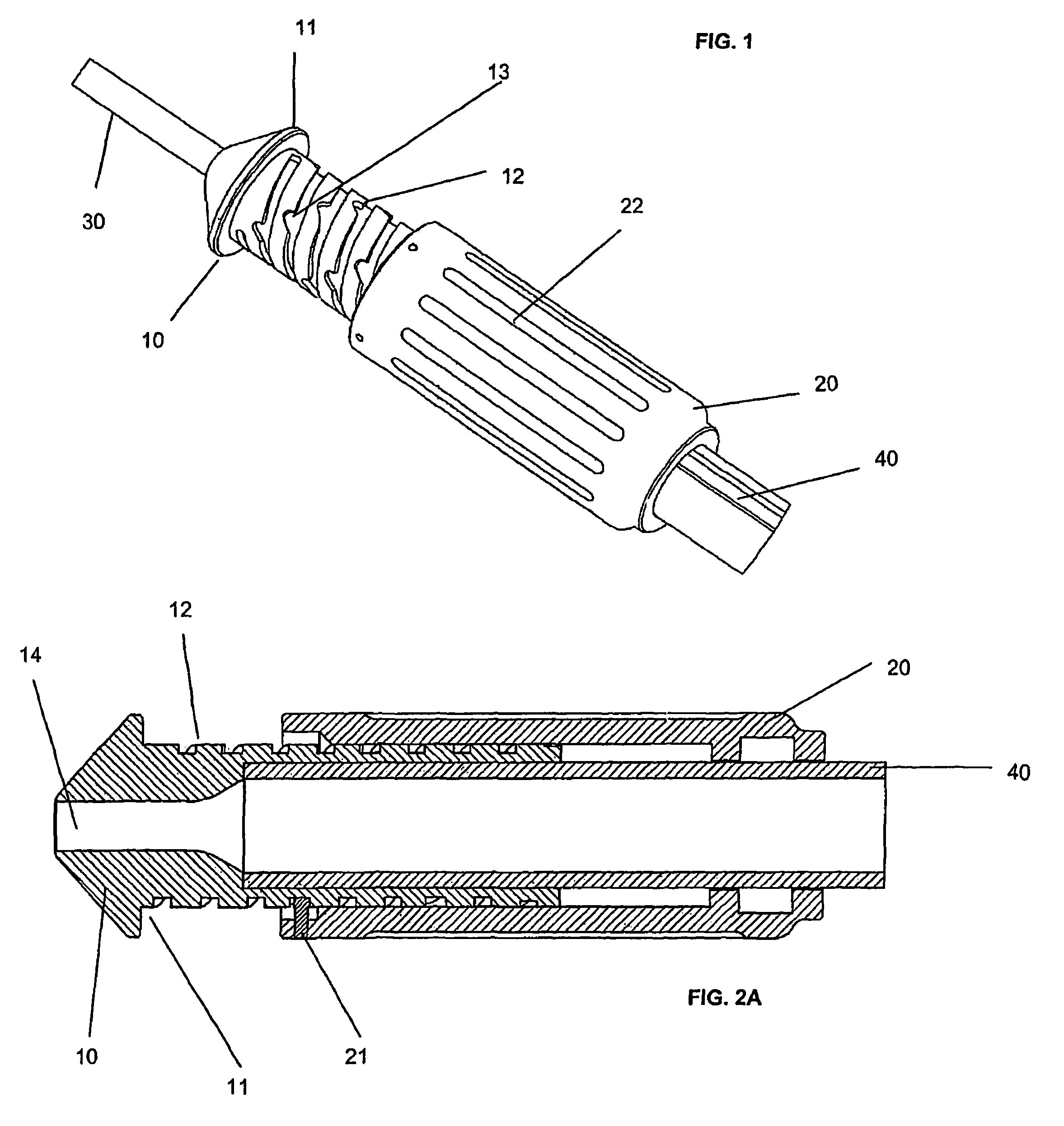
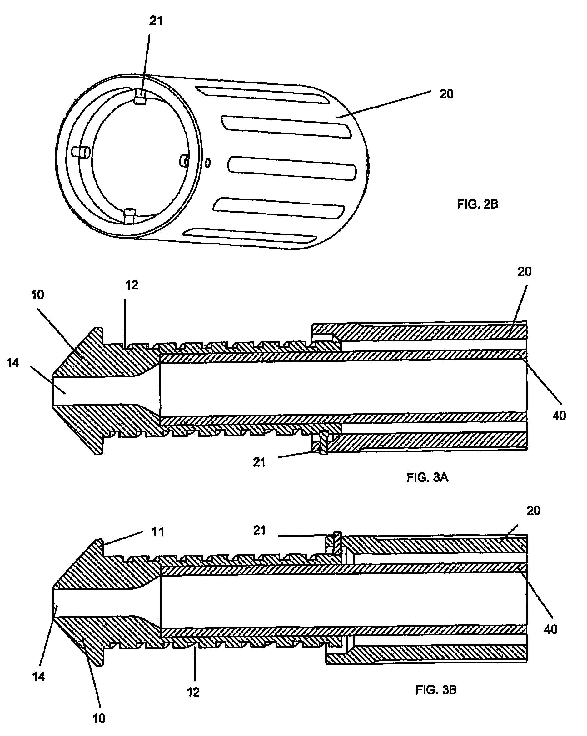
[0027]The control mechanism comprises a handle (10) which is an elongate element with a central bore (14) through which delivery catheter (30) can pass. The outside surface of handle (10) has thread (12) with a plurality of steps (13) therein and a stop (11) at one end of handle (10).

[0028]Barrel (20) has four pins (21) projecting from its inner surface, pins (21) engaging with thread (12) to enable barrel (20) to be threaded axially over the external surface of handle (10).

[0029]The external surface of barrel (20) has a hand grip (22) to enable the user to grip barrel (20) and rotate it about handle (10).

[0030]Pins (21) are mounted in four holes (not shown) in barrel (20) and are able to move radially from a position of maximum projection into the centre of barrel (20) to a position of radial retraction and minimal projection into the centre of barrel (20). This enables pins (21) to engage and disengage with thread (12) as will be described below.

[0031]Catheter delivery tube (40) i...


PUM


Abstract

A control mechanism comprises an elongate handle 10 having an external thread 12 and a barrel 20 with internally projecting pins 21 threaded over handle 10. Rotation of barrel 20 causes handle 10 to move back and forth along its longitudinal axis to retract and advance a catheter sheath to which handle 10 is coupled, thereby enabling an implant to be deployed by the catheter. Rotation movement of barrel 20 and longitudinal movement of handle 10 can be disassociated to enable speedy retraction or advancement of the catheter sheath.

Description

FIELD OF THE INVENTION[0001]The present disclosure relates to an improved mechanism for controlling medical catheters and more particularly those catheters which are used to deliver implants to particular sites within a patient's body, such as cardiovascular stents. The system has applications in a wide range of catheter or laparoscopic surgery and is of particular value in delivering larger implants, such as stent grafts, within arteries.BACKGROUND OF THE INVENTION[0002]Catheter delivery systems usually comprise a sheath at whose tip is contained the device to be implanted. The device is usually highly compressed, particularly in diameter, and the device is released by drawing the sheath back, allowing the device to emerge from its tip. All designs feature a structure which provides a reaction force for the device so that it maintains its position while the sheath is being withdrawn.[0003]A simple example of this type of delivery system is provided with the Talent™ stent-graft manu...

Claims


Application Information

Patent Timeline
Patent Type & Authority Patents(United States)
IPC IPC(8): A61F2/06A61F2/95A61M25/01
CPCA61F2/95A61F2002/9517A61F2/9517
Inventor KEEBLE, DUNCAN R.JONES, ANTHONYPHILLIPS, PETER W.
Owner ANSON MEDICAL LTD
Why Eureka
Try Eureka