Hydraulic System For A Transmission With Pump Inlet Diffuser

a technology of hydraulic system and transmission pump, which is applied in the direction of positive displacement liquid engine, separation process, filtration separation, etc., can solve the problems of hydraulic system feeding the pump reaching a high speed fill limit, creating a very large potential flow volume at high speeds, and insufficient to keep the pump chambers full, so as to reduce cavitation and increase the efficiency of flow through the filter outlet portion , the effect of high pump speed

Active Publication Date: 2010-05-06
GM GLOBAL TECH OPERATIONS LLC
View PDF1 Cites 17 Cited by
  • Summary
  • Abstract
  • Description
  • Claims
  • Application Information

AI Technical Summary

Benefits of technology

[0005]An improved hydraulic system is provided that is especially useful for decreasing cavitation at high pump speeds even in relatively small fixed displacement pumps. Specifically, a hydraulic system for a transmission is provided that has a housing, referred to herein as a diffuser housing, with a fluid inlet passage that feeds one or more pump inlet port(s), and a fluid return passage, such as to return fluid from a pressure regulator valve, that is in fluid communication with the fluid inlet passage. The hydraulic system also has a filter housing with a filter outlet portion that is in fluid communication with the fluid inlet passage upstream of the pump inlet port(s). The fluid return passage is downstream of the filter outlet portion. Thus,

Problems solved by technology

However, sizing the pump to satisfy a low speed condition will create very large potential flow volume at high speeds.
The hydraulic system feeding the pump may reach a high speed fill limit, i.e., a maximum fluid input into the pump is reached and is insufficient to keep the pump chambers full at high speeds.
This will cause incomplete filling of the ch

Method used


Image

  • Hydraulic System For A Transmission With Pump Inlet Diffuser
  • Hydraulic System For A Transmission With Pump Inlet Diffuser
  • Hydraulic System For A Transmission With Pump Inlet Diffuser

Examples


Embodiment Construction

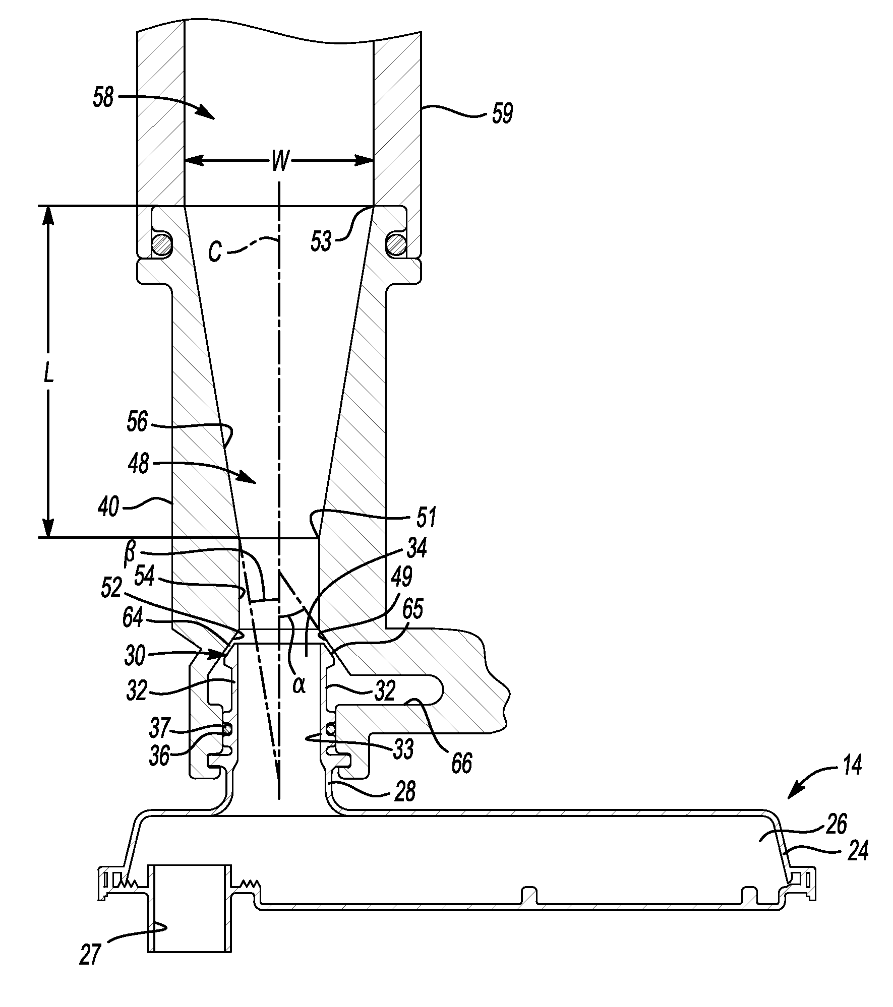
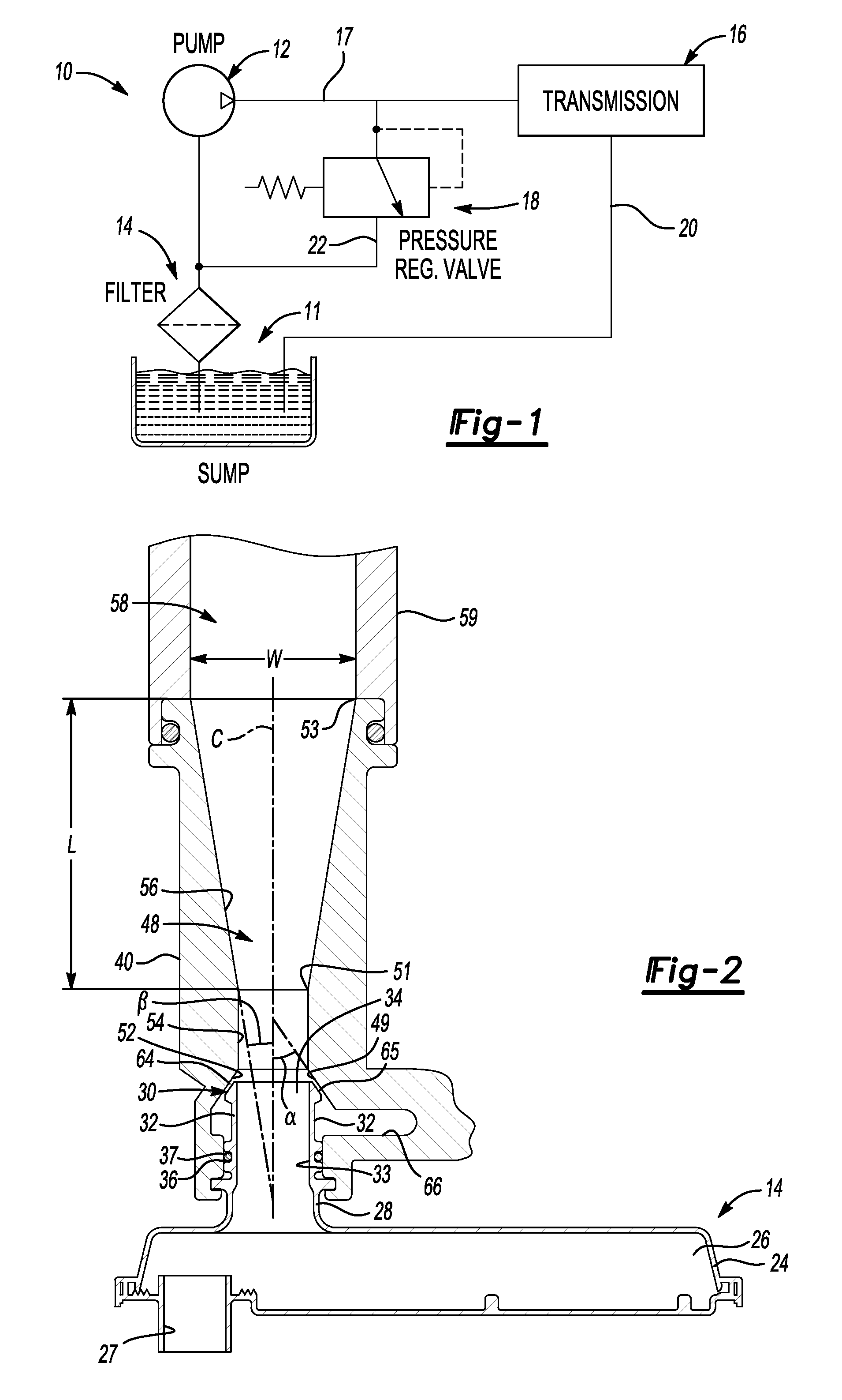
[0015]Referring to the drawings, wherein like reference numbers refer to like components, there is seen in FIG. 1 a schematic representation of a hydraulic system 10 including a sump or reservoir 11 which contains hydraulic fluid. A transmission control pump 12 draws fluid from the reservoir 11 through a filter assembly 14. The pump 12 delivers pressurized hydraulic fluid to a transmission 16. The maximum pressure at the pump outlet 17 is determined by a pressure regulator valve 18, which delivers excess pump flow back to the outlet of the filter assembly 14. The pumped fluid first satisfies the transmission oil demand, including any clutch pressure requirements, then satisfies torque converter pressure requirements, if a torque converter is present in the transmission 16, then supplies lubrication and cooling, and finally the excess fluid is returned to the filter assembly 14 through passages such as 20.

[0016]The excess flow from the pressure regulator valve 18 is delivered to the ...


PUM

PropertyMeasurementUnit
Angleaaaaaaaaaa
Angleaaaaaaaaaa
Angleaaaaaaaaaa

Abstract

A hydraulic system for a transmission has a diffuser housing with a fluid inlet passage that feeds one or more pump inlet ports, and a fluid return passage, such as to return fluid from a pressure regulator valve, that is in fluid communication with the fluid inlet passage. The hydraulic system also has a filter housing with a filter outlet portion that is in fluid communication with the fluid inlet passage upstream of the pump inlet port(s). The fluid return passage is downstream of the filter outlet portion. Thus, flow through the fluid return passage can create suction, causing increased flow through the filter outlet portion, such as from a fluid sump. Specifically, the diffuser housing is configured so that the fluid inlet passage has a converging portion downstream of the filter outlet portion and a diverging portion downstream of the converging portion.

Description

TECHNICAL FIELD[0001]The invention relates to a transmission hydraulic system with a diffuser for a pump inlet of a transmission pump.BACKGROUND OF THE INVENTION[0002]A fixed displacement pump has a theoretical fixed output of oil for each revolution of the pump, assuming the pump chambers are completely filled. The pump thus has an output proportional to the speed of the pump. An engine driven pump for a transmission will thus have a wide output range dependent on engine speed. The pump must be sized for the most demanding application, which is a low speed garage shift when high output volume is required at low speed. The pump must be filled adequately at such a low speed in order to sufficiently pressurize the transmission in order to accomplish the shift. However, sizing the pump to satisfy a low speed condition will create very large potential flow volume at high speeds. The hydraulic system feeding the pump may reach a high speed fill limit, i.e., a maximum fluid input into the...

Claims


Application Information

Patent Timeline
IPC IPC(8): F04B53/16F04B53/20
CPCF16H57/0402F16H57/0408F16H57/0441
Inventor SCHULTZ, JOHN C.
Owner GM GLOBAL TECH OPERATIONS LLC
Why Eureka
Try Eureka