Variable valve timing for cylinder deactivation

a variable valve timing and cylinder technology, applied in the direction of process and machine control, electrical control, instruments, etc., can solve the problems of net flow between the intake and exhaust manifold, tailpipe emissions and catalyst efficiency, fuel economy penalty, etc., to improve engine performance, increase positive or negative valve overlap, increase negative valve overlap

Active Publication Date: 2014-01-30
FORD GLOBAL TECH LLC
View PDF19 Cites 16 Cited by
  • Summary
  • Abstract
  • Description
  • Claims
  • Application Information

AI Technical Summary

Benefits of technology

[0002]Engines may be operated with variable valve timing control to improve engine performance. For example, intake and/or exhaust valve timings may be adjusted (e.g., advanced or retarded) based on engine operating conditions to increase positive or negative valve overlap. Increased positive valve overlap may be used for improving air-fuel mixing and cylinder charge t

Problems solved by technology

However, the inventors herein have identified potential issues with such an approach.
As one example, there may be tailpipe emissions and catalyst efficiency issues.
This results in a fuel economy penalty.
In the same way, minor changes in exha

Method used


Image

  • Variable valve timing for cylinder deactivation
  • Variable valve timing for cylinder deactivation
  • Variable valve timing for cylinder deactivation

Examples


Embodiment Construction

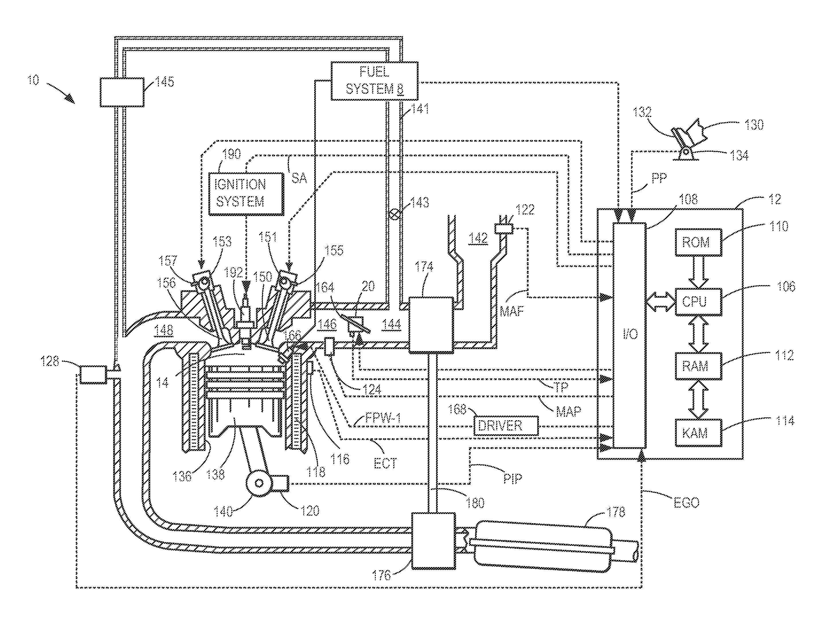
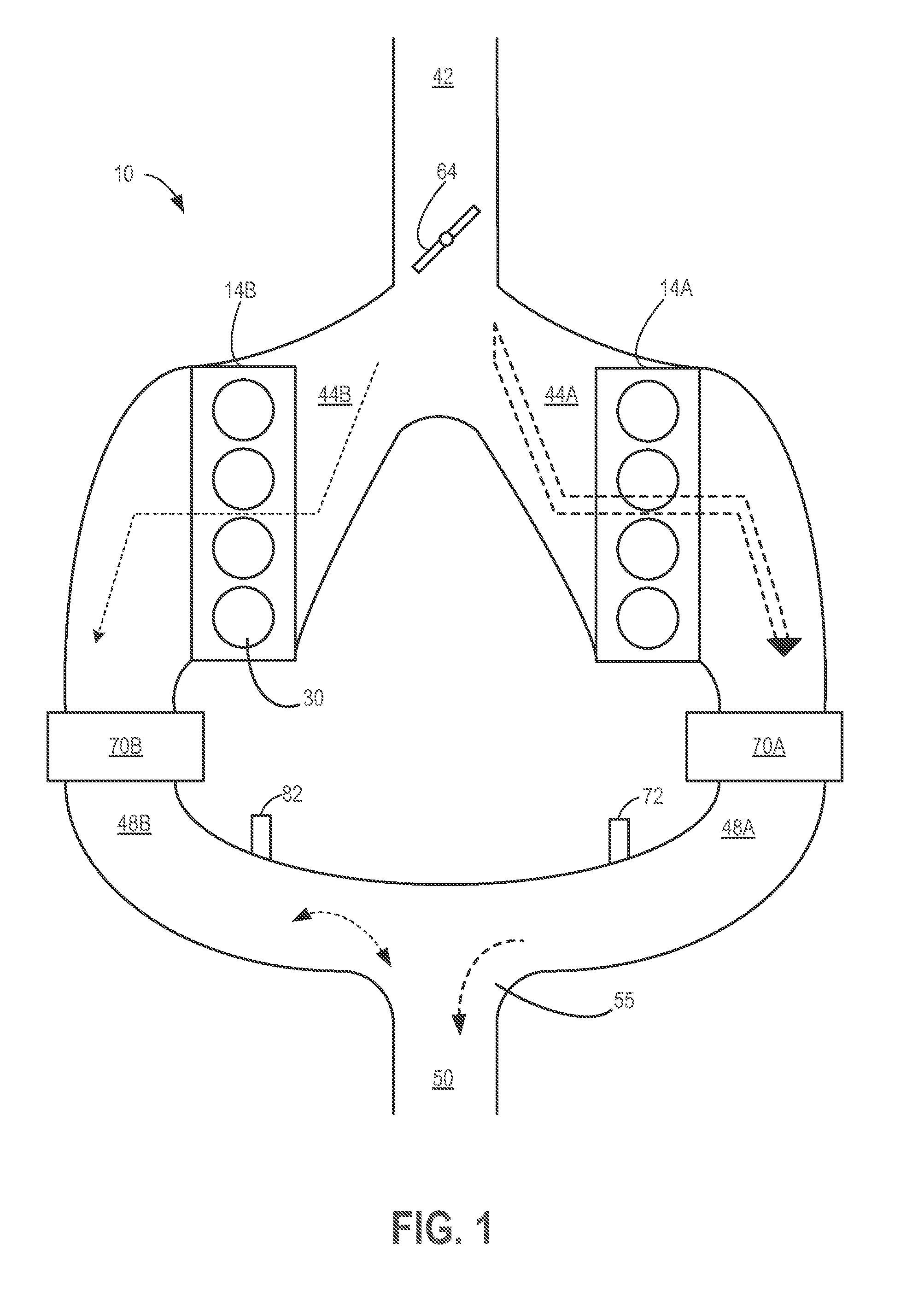
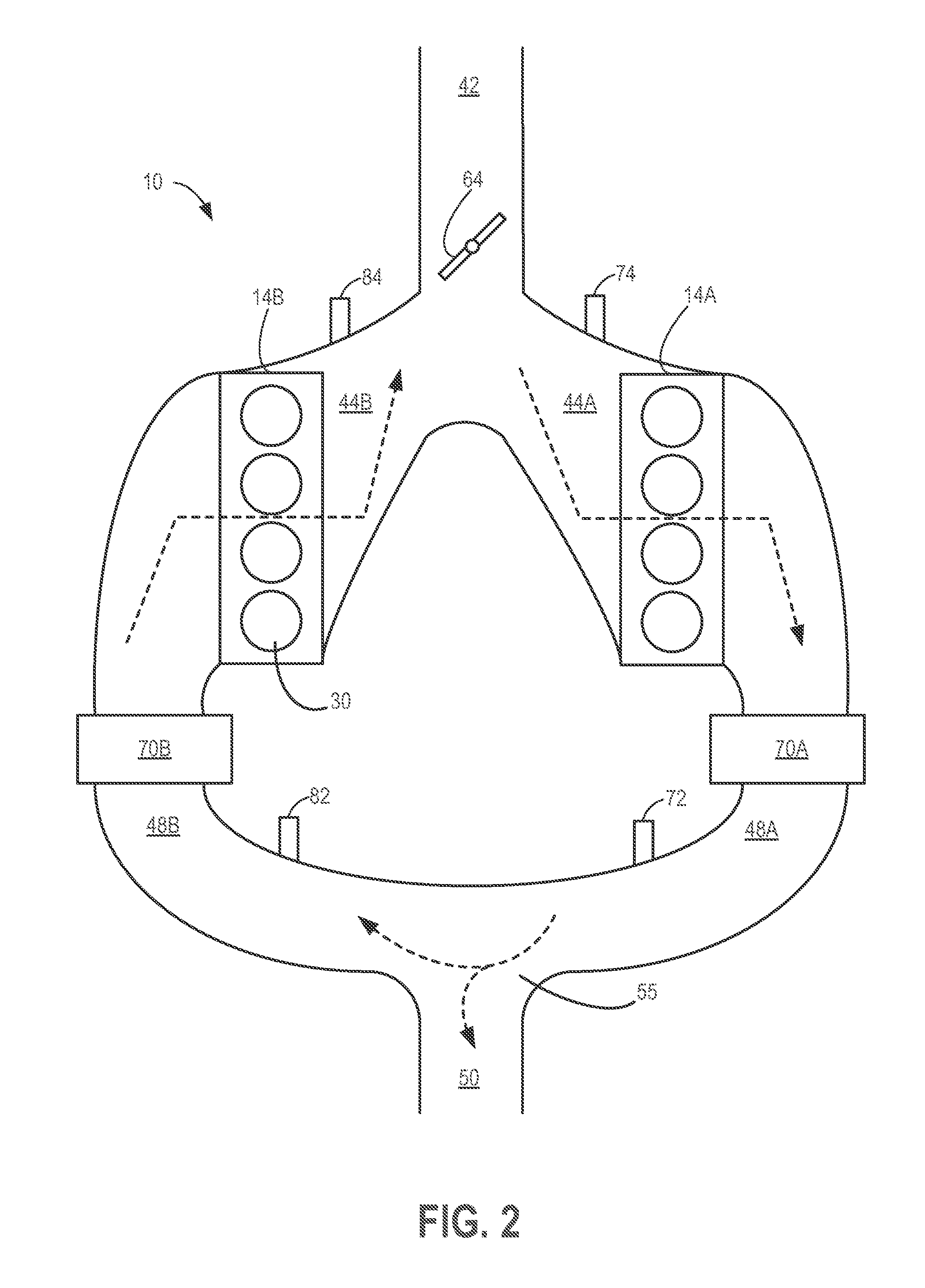
[0015]The following description relates to systems and methods for adjusting intake and / or exhaust valve timing for a first group of cylinders on a first engine bank and a second group of cylinders on a second engine bank (FIGS. 1-3) to enable selective cylinder deactivation. A controller may be configured to perform control routines, such as those shown at FIGS. 4-6, to direct substantially less flow, in the same direction, through an inactive bank as compared to an active bank during some operating conditions. During other conditions, the controller may direct combusted exhaust gas from the active bank through the inactive bank, in the opposite direction. As shown at FIG. 7, the controller may also detect exhaust leaks in the inactive bank during the reversed flow based on changes in monitored air-to-fuel ratio. By adjusting the valve timing of the inactive bank based on an exhaust air-to-fuel ratio of the inactive bank, cylinder deactivation benefits may be achieved while maintai...


PUM


Abstract

Methods and systems are provided for adjusting cylinder valve timings to enable a group of cylinders to operate and combust while another group of cylinders on a second are selectively deactivated. Valve timing may be adjusted to allow flow of air through the inactive cylinders to be reduced, lowering catalyst regeneration requirements upon reactivation. The valve timing may alternatively be adjusted to enable exhaust gas to be recirculated to the active cylinders via the inactive cylinders, providing cooled EGR benefits.

Description

TECHNICAL FIELD[0001]This application relates to varying a valve timing to achieve virtual cylinder deactivation and selectively enable reverse flow through a deactivated cylinder bank to achieve EGR benefits.BACKGROUND AND SUMMARY[0002]Engines may be operated with variable valve timing control to improve engine performance. For example, intake and / or exhaust valve timings may be adjusted (e.g., advanced or retarded) based on engine operating conditions to increase positive or negative valve overlap. Increased positive valve overlap may be used for improving air-fuel mixing and cylinder charge temperature control, for example. As another example, increased negative valve overlap may be used so that flow of air through one or more engine cylinders (e.g., on one engine bank) is substantially reduced while flow of air through other cylinders (e.g., on another bank) is allowed. This enables selective deactivation of the cylinders on the bank with the reduced flow.[0003]However, the inve...

Claims


Application Information

Patent Timeline
IPC IPC(8): F02D13/00F02D41/26
CPCF02D13/0207F02D13/0219F02D19/084F02D41/006F02D41/0082F02D41/0002F02D41/005F02D2041/001F02M26/43F02M26/46F02M26/05F02M26/06F02M26/47F02D13/06Y02T10/12Y02T10/40Y02T10/30
Inventor KERNS, JAMES MICHAELSMITH, STEPHEN B.BANKER, ADAM NATHANUHRICH, MICHAEL JAMES
Owner FORD GLOBAL TECH LLC
Why Eureka
Try Eureka