Main shaft locking mechanism

Inactive Publication Date: 2011-02-10
TOP GEARBOX IND +1
View PDF11 Cites 12 Cited by
  • Summary
  • Abstract
  • Description
  • Claims
  • Application Information

AI Technical Summary

Benefits of technology

[0007]A primary objective of the present invention is to provide a main shaft locking mechanism to overcome the aforementioned disadvantage of unsatisfactory concentricity between a main shaft and a fixing ring which impairs the locking effect.

Problems solved by technology

Therefore the exterior sides of the detents interfere with the fixing ring so that the detents endure a counterforce from the fixing ring to drive the detents to counter rotate.

Method used


Image

  • Main shaft locking mechanism
  • Main shaft locking mechanism
  • Main shaft locking mechanism

Examples


Embodiment Construction

[0018]The accompanying drawings are included to provide a further understanding of the invention, and are incorporated in and constitute a part of this specification. The drawings illustrate an embodiment of the invention and, together with the description, serve to explain the principles of the invention.

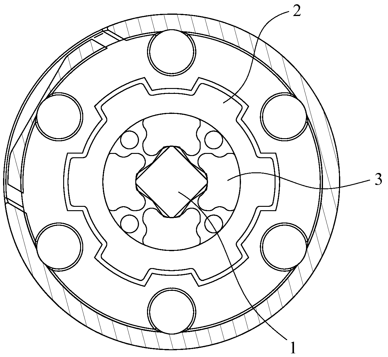
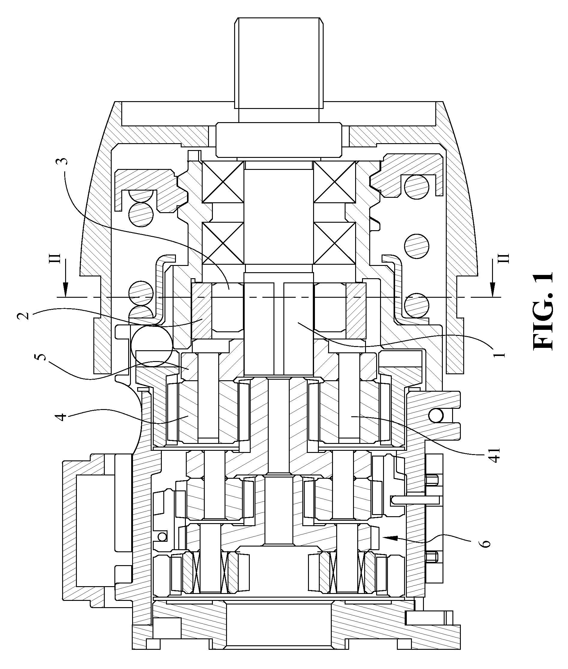
[0019]FIG. 1 is a cross sectional view showing a main shaft locking mechanism of a power tool according to an embodiment of the present invention. FIG. 2 is a cross sectional view showing the main shaft locking mechanism taken along line II-II of FIG. 1, looking in the direction of the arrows. Referring to FIGS. 1 and 2, the main shaft locking mechanism according to the present invention includes a main shaft 1, a fixing ring 2, a plurality of detents 3, a planetary gear set 4, a driving plate 5 and a gear reduction unit 6. The main shaft 1 is assembled with a bearing that is disposed in a housing of the power tool. The main shaft 1 is adapted for being driven to rotate. A front en...


PUM

PropertyMeasurementUnit
external forceaaaaaaaaaa
poweraaaaaaaaaa
torqueaaaaaaaaaa

Abstract

A main shaft locking mechanism includes a fixing ring, a main shaft and detents. The main shaft includes an equilateral portion that has an equilateral cross section. A number of the corners of the equilateral portion is equal to that of the detents. The detent has an exterior side and an interior side opposite to the exterior side. The interior side includes two corner protrusions protruded out from two ends thereof and a concave portion defined between the two corner protrusions. The corners of the main shaft are received in the concave portions of the detents. When the main shaft is manually driven to rotate, the corners of the main shaft drive the detents to deviate. Therefore, the exterior sides of the detents interfere against the fixing ring. Then the detents prevent the main shaft from further rotating, thus locking up the main shaft.

Description

BACKGROUND OF THE INVENTION[0001]1. Field of the Invention[0002]The present invention relates generally to a main shaft locking mechanism applicable for a power tool, according to which when the power tool is not provided with power supply, the main shaft of the power tool is prevented from being rotated by any external force.[0003]2. The Prior Arts[0004]A conventional power tools, e.g., a power drill, is typically driven by electric power, and can be classified into corded, cordless (chargeable) or both. Generally, the power tool not only can hold a drilling bit for forming a hole, but also can hold a screwdriver bit to screw or unscrew a screw. Usually, the corded power tool is more powerful than the cordless power tool and is more suitable for heavy duty. However, when the power tool is used in places without any socket, the cordless power tool driven by a chargeable battery is the only option. Unfortunately, when the battery is running low and is unable to recharge, the cordless...

Claims


Application Information

Patent Timeline
Patent Type & Authority Applications(United States)
IPC IPC(8): B25F5/00B23B45/02
CPCB23B45/008Y10T408/65B25F5/001B25B21/00
Inventor CHEN, TING-KUANG
Owner TOP GEARBOX IND
Why Eureka
Try Eureka