Adjustable Steering Column Assembly

a technology of steering column and assembly, which is applied in the direction of steering parts, vehicle components, transportation and packaging, etc., can solve the problems of permanent damage to the tips of the teeth, and the strength alone is often insufficient,

Active Publication Date: 2011-02-24
TRW LIMITED
View PDF13 Cites 64 Cited by
  • Summary
  • Abstract
  • Description
  • Claims
  • Application Information

AI Technical Summary

Benefits of technology

[0007]It is a feature of the present invention is to provide a steering column assembly including a clamp mechanism that at least partially ameliorates this tooth-on-tooth problem.

Problems solved by technology

For this, friction alone is often insufficient, as massive clamp forces would be needed to achieve this.
There is a well known problem with the type of “Positive-Locking” column which uses rows of inter-engaging teeth whereby, prior to operation of the locking lever by the driver, the selected steering wheel position has resulted in exact alignment of the tips of one row of teeth with those of the set of teeth with which they are supposed to engage.
Inter-engaging of the teeth during the clamping operation is thereby blocked and, if excessive force is applied by the driver to the clamp lever to force it to complete its travel, permanent damage can occur to the tips of the teeth.
This is undesirable.

Method used


Image

  • Adjustable Steering Column Assembly
  • Adjustable Steering Column Assembly
  • Adjustable Steering Column Assembly

Examples


Embodiment Construction

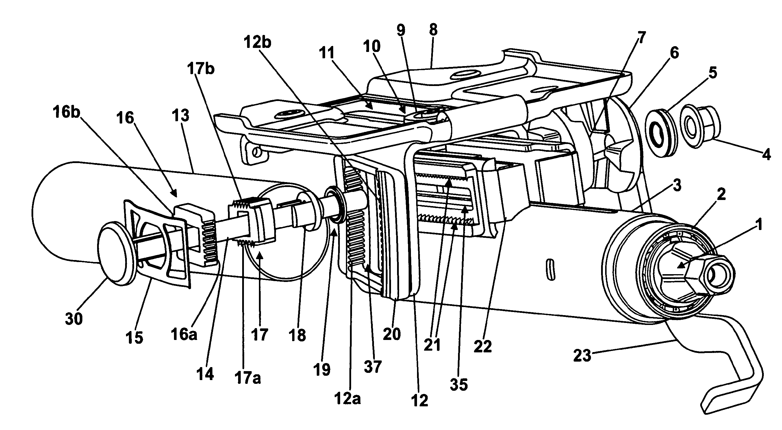
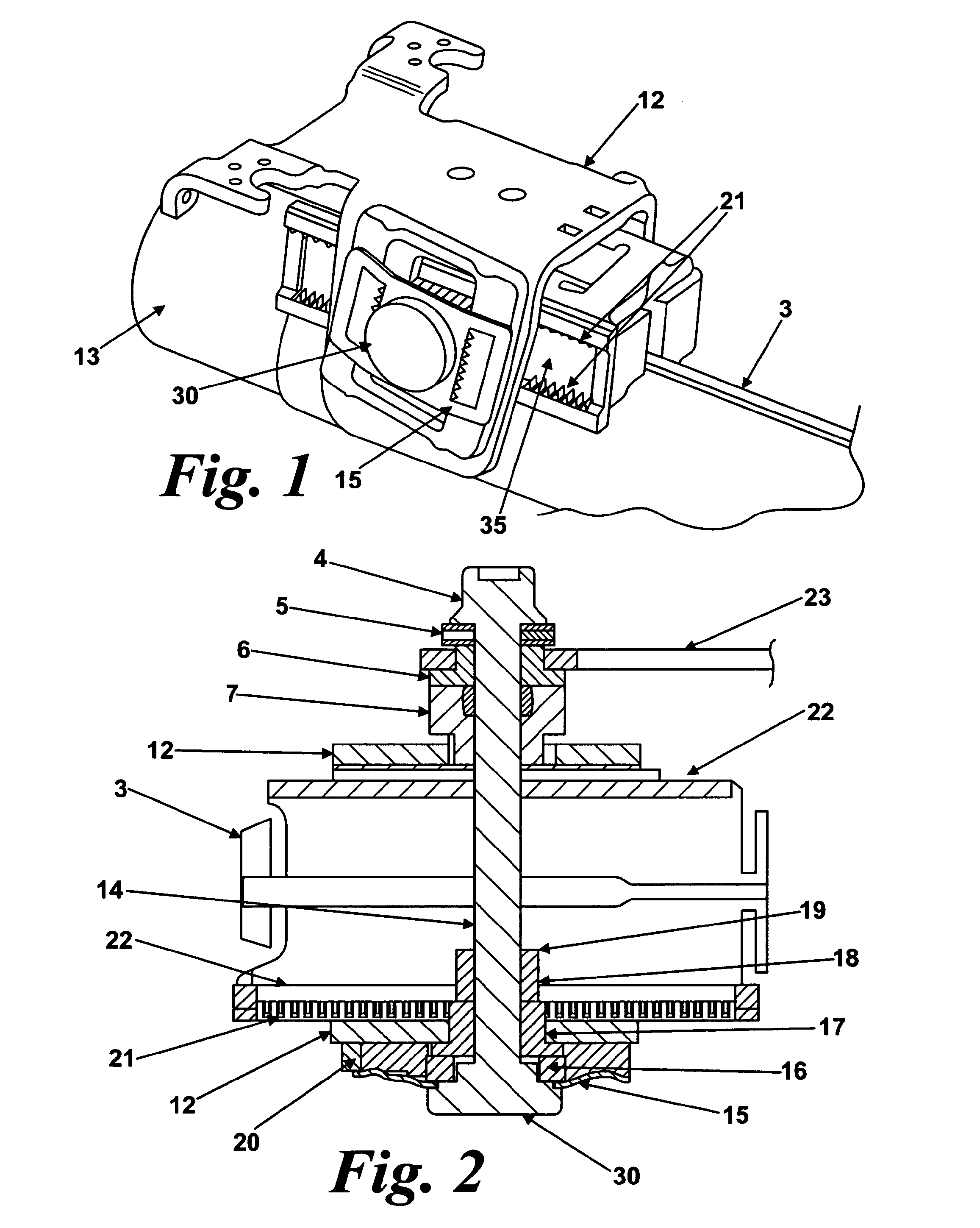
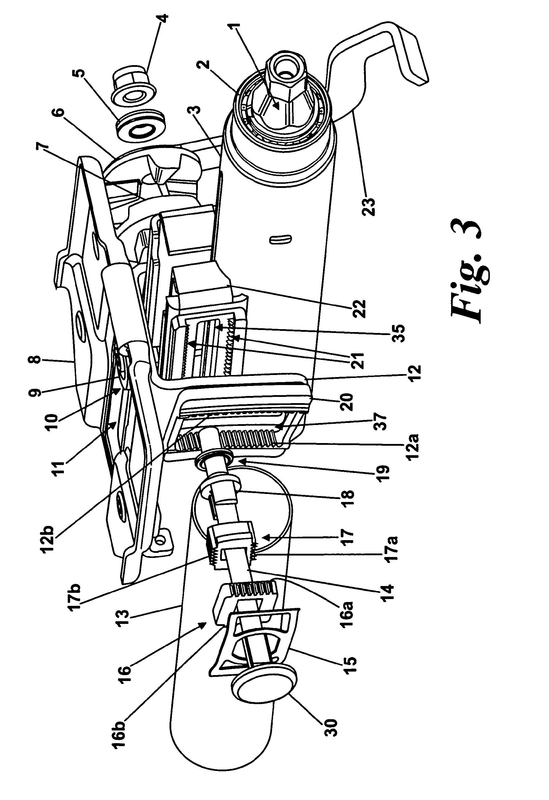
[0047]FIGS. 1 and 2 of the accompanying drawings show an embodiment of the invention applied to a so-called double-adjustment type steering column. Such columns can be adjusted for both reach (in and out) and rake angle (up and down). The column assembly comprises an upper column body assembly 3 and a lower column body assembly 13 which can telescope relative to one another to allow for reach adjustment and which can both be moved in an arc around a pivot point axis to allow for rake adjustment. The telescoping mechanism allows the adjustment of the Reach position by the driver and also allows the Outer Shroud to move forward in a controlled manner in the event of the steering wheel (not shown) being impacted by the driver in a crash.

[0048]A first portion, so called upper column body assembly 3, comprises an outer tubular shroud which supports the steering wheel shaft 1 via a ball bearing 2 (see FIG. 3). A second portion, so called lower column body assembly 13, comprises an inner t...


PUM


Abstract

An adjustable steering column assembly includes a fixed rack secured to a first portion and a moving rack secured to a second portion, which are releasably engaged by a clamp mechanism to permit relative movement therebetween. The fixed rack comprises two rows of teeth spaced apart from one another and extending towards. The moving rack also comprises two rows of teeth which extend away from each other. A clamp engaging means moves the moving rack into and out of engagement with the fixed rack. The teeth on the two racks are offset relative to one another. The mechanism is further arranged so that when if a tooth on tooth event occurs the fixed rack interacts with the moving rack to cause the moving rack to move sideways to permit the teeth to become inter-engaged when the mechanism finally reaches the locked position.

Description

CROSS-REFERENCE TO RELATED APPLICATIONS[0001]This application is a national stage of International Application No. PCT / EP2008 / 066435 filed Nov. 28, 2008, the disclosures of which are incorporated herein by reference in entirety, and which claimed priority to Great Britain Patent Application No. 0723485.9 filed Nov. 30, 2007, the disclosures of which are incorporated herein by reference in entirety.BACKGROUND OF THE INVENTION[0002]The invention relates to adjustable steering column assemblies of the kind that use rows of inter-engaging teeth for the purpose of positively locking the steering wheel at various up / down (rake) and / or in / out (reach) positions.[0003]Steering column assemblies are known which include a clamp mechanism that relies solely on friction when locked to prevent unwanted movement of the column assembly. The clamp mechanism can be unlocked and locked by movement of a locking lever or, sometimes, electrically using a motor or perhaps hydraulically or pneumatically. T...

Claims


Application Information

Patent Timeline
Patent Type & Authority Applications(United States)
IPC IPC(8): B62D1/184
CPCB62D1/195B62D1/184
Inventor HAVLICEK, JAN
Owner TRW LIMITED
Why Eureka
Try Eureka