Universal motor

a technology of universal motors and wire windings, applied in current collectors, dynamo-electric machines, dynamo-electric components, etc., can solve problems such as material waste, and achieve the effect of improving the material usage of wire windings

Inactive Publication Date: 2011-02-24
JOHNSON ELECTRIC SA
View PDF11 Cites 21 Cited by
  • Summary
  • Abstract
  • Description
  • Claims
  • Application Information

AI Technical Summary

Benefits of technology

[0004]Hence there is a desire for a universal motor which has improved material usage of the wire of the windings.

Problems solved by technology

That is, the length of the wire in the turns of the coils near the outside of the coil is substantially larger than the first wound turns which results in waste of material.

Method used


Image

  • Universal motor
  • Universal motor
  • Universal motor

Examples


Embodiment Construction

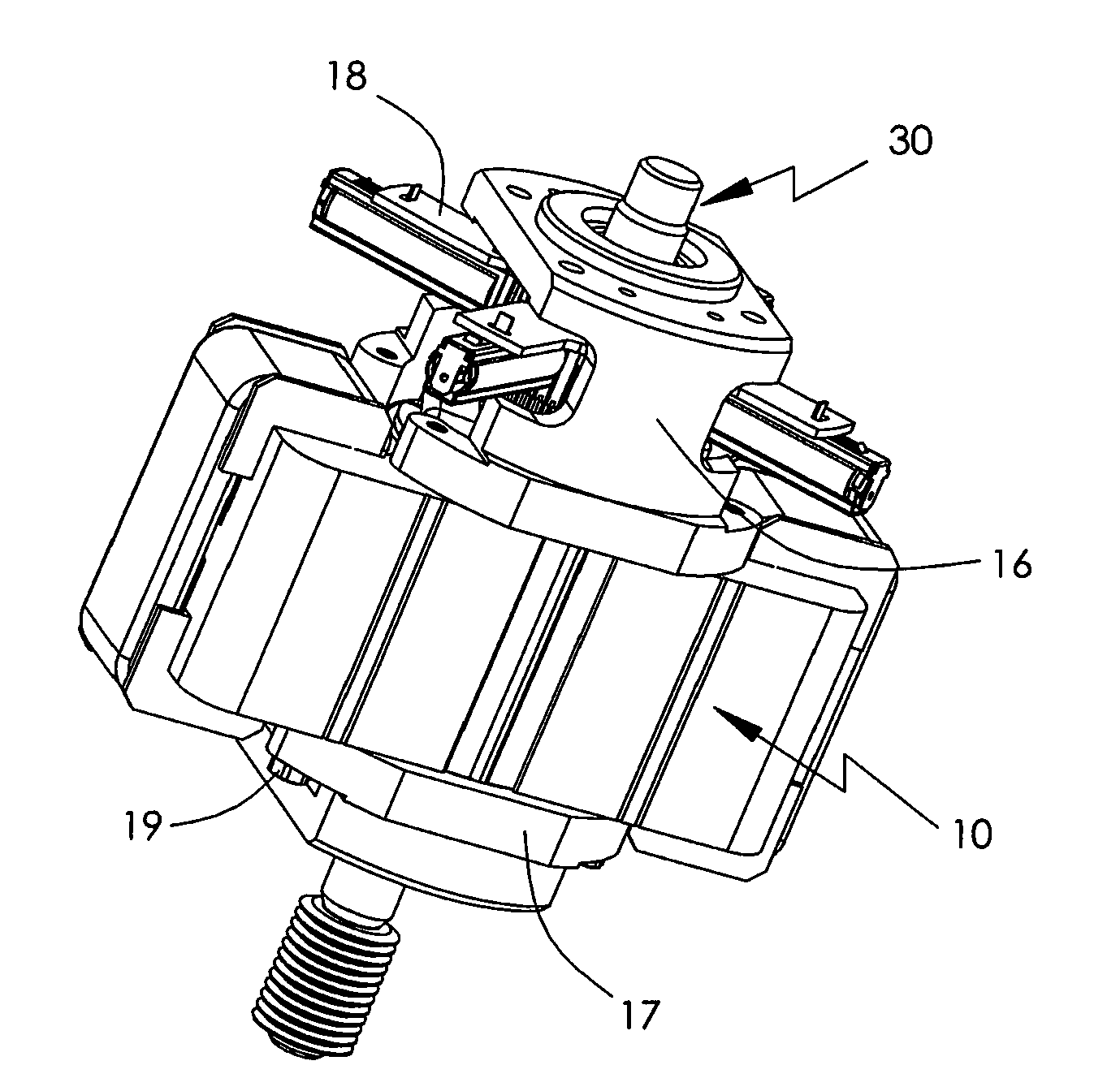
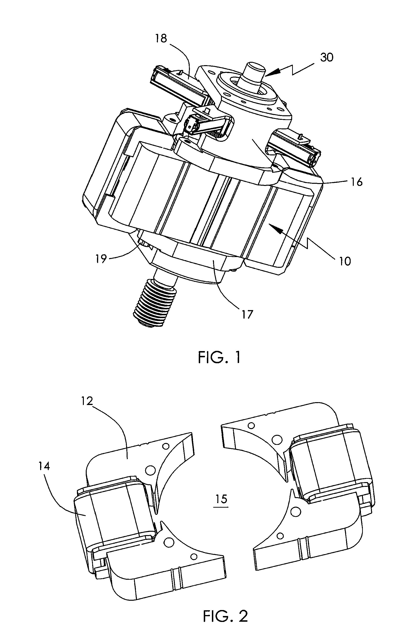
[0026]FIGS. 1 to 5 illustrate a universal motor according to a first preferred embodiment of the present invention, having a stator 10 and a rotor 30 rotatably mounted relative to the stator 10.

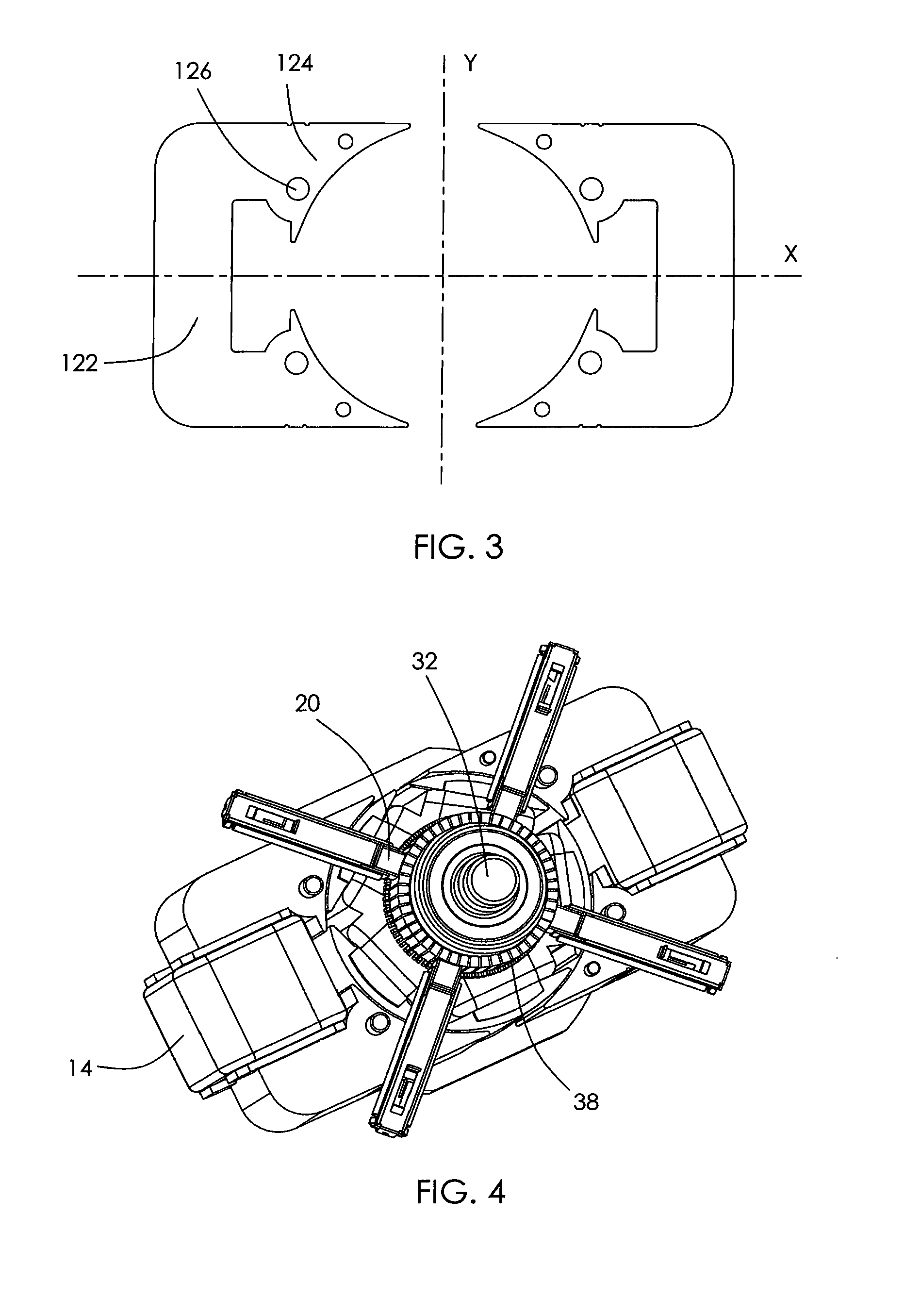
[0027]As shown more clearly in FIGS. 2 and 3, the stator 10 comprises a pair of symmetrical C-shaped stator cores 12 and two windings 14 respectively wound on the stator cores 12. Each stator core 12 comprises a yoke 122 and a pair of poles 124 extending from opposite ends of the yoke 122. The windings 14 are wound on the respective yokes 122. Each pole 124 has a curved pole face and the pole faces cooperatively define an opening 15. The two stator cores 12 are separately formed and arranged symmetrical to each other about a first axis Y which extends in a width direction of the stator 10. Each stator core 12 is symmetrical about a second axis X which extends in a length direction of the stator 10. The axis X is perpendicular to the axis Y, and crosses the axis Y at the rotational axis of the...


PUM


Abstract

A universal motor has a rotor and a stator. The stator comprises a pair of symmetrical C-shaped stator cores and two windings respectively wound on the stator cores. Each stator core comprises a yoke and a pair of poles extending from opposite ends of the yoke. The windings are wound on the yokes. Each pole has a curved surface and the surfaces of the poles cooperatively form an opening. The rotor is rotatably received in the opening.

Description

CROSS REFERENCE TO RELATED APPLICATIONS[0001]This non-provisional patent application claims priority under 35 U.S.C. §119(a) from Patent Application No. 200910109379.9 filed in The People's Republic of China on Aug. 21, 2009 and from Patent Application No. 201010251472.6 filed in The People's Republic of China on Aug. 10, 2010.FIELD OF THE INVENTION[0002]This invention relates to a universal motor and in particular, to a universal motor having a split stator.BACKGROUND OF THE INVENTION[0003]FIG. 9 shows a conventional universal motor which comprises a stator and a rotor (not shown). The stator comprises a stator core 12′ and windings 14′. The stator core 12′ comprises a square yoke with four sides and four poles 124′ each extending inwardly from a corresponding side in radial directions. The poles have a neck which joins the pole to the yoke. The windings 14′ are wound on the necks. In order to allow the rotor to have a large diameter, the necks have a small length in the radial dir...

Claims


Application Information

Patent Timeline
Patent Type & Authority Applications(United States)
IPC IPC(8): H02K23/64
CPCH02K1/141H02K23/40H02K5/148
Inventor LI, YUEJIANG, MAO XIONGLIU, LI SHENGZHAO, JIANLI, YONG
Owner JOHNSON ELECTRIC SA
Why Eureka
Try Eureka