Electric double layer capacitors, capacitor materials and methods of making the same

a capacitor material and double layer technology, applied in the field of carbon materials and methods, can solve the problems of insufficient energy density range or practicality for high-energy applications, and achieve the effect of improving the previous carbon materials used

Inactive Publication Date: 2008-01-31
CORNING INC
View PDF23 Cites 9 Cited by
  • Summary
  • Abstract
  • Description
  • Claims
  • Application Information

AI Technical Summary

Benefits of technology

[0006]The present invention is intended to address and obviate problems and shortcomings and otherwise improve previous carbon materials used in EDLC devices, and thus EDLC devices in general.

Problems solved by technology

However, this energy density range is not sufficient or practical for high energy applications, such as for hybrid vehicles.

Method used


Image

  • Electric double layer capacitors, capacitor materials and methods of making the same
  • Electric double layer capacitors, capacitor materials and methods of making the same
  • Electric double layer capacitors, capacitor materials and methods of making the same

Examples


example 1

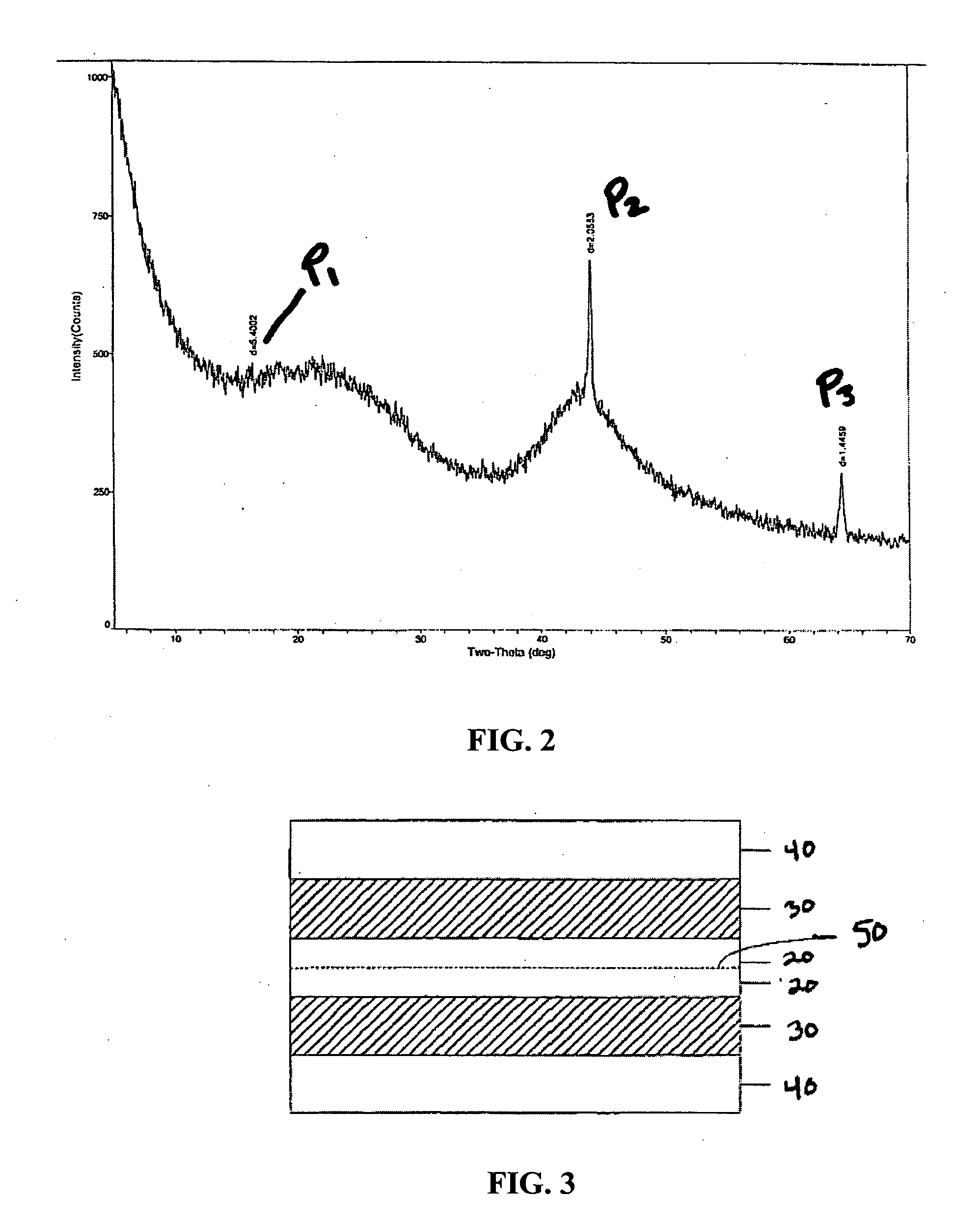
[0041]Three hundred grams of 45 wt % NaOH solution in water was mixed with 100 grams of synthetic phenolic resole resin which contains about 70% resin in 30% water. The mixture was subsequently dried and cured at 180° C. to form a sponge like mass. This mass was heated in nitrogen up to 800° C. for two hours to carbonize the resin. The carbonized resin was subsequently steam treated to remove the sodium from the carbon. This carbon was then ground to approximately 10 micron mean particle size. The carbon was mixed with 10 grams of carbon black and 10 grams of PTFE to obtain a well mixed mass. This mixture was subsequently rolled on a roll mill to obtain a thin film approximately 50 microns thick. From the film obtained, carbon electrodes were stamped out.

[0042]The electrodes were then soaked with an electrolyte solution (1M TEA-TFB in acetonitrile). A porous separator was also soaked in the electrolyte solution and the two carbon electrodes with the separator in between were assembl...

example 2

[0043]The experiment of Example 1 was repeated, but instead of using carbon materials manufactured by processes herein, a standard conventional commercial carbon was used. Particularly, a carbon from PICA USA Inc., Columbus, Ohio, specially developed for EDLC applications was utilized. Standard voltametric as well galvanostatic tests were carried out to measure the performance of the cell. The measured energy density of the device was 6 Wh / l and the specific power was 3707 W / Kg. The BET surface area of this carbon was 1800 m2 / g. FIG. 5 shows the result of measurement for the low angle X-ray diffraction pattern on the carbon of this example. The peak P2′, exists at the position of two-theta of about 1.5°. More importantly, P2′ has an interlayer distance (d) of 57.32.

example 3

[0044]The experiment of Example 1 was repeated, but instead of using 45 wt % NaOH solution, 45% wt KOH solution was utilized. Standard voltametric as well galvanostatic tests were carried out to measure the performance of the cell. The measured energy density of the device was 15.6 Wh / l and the specific power was 6518 W / kg. FIG. 6 shows the low angle X-ray diffraction pattern of the carbon obtained in Example 3 The peaks P1′, exists at the position of two-theta of about 1°. Moreover, P3′ has an interlayer distance (d) of 95.95.


PUM

PropertyMeasurementUnit
energy densityaaaaaaaaaa
temperaturesaaaaaaaaaa
energy densityaaaaaaaaaa

Abstract

Carbon materials and methods of manufacturing carbon materials for use in high energy devices, such as electric double layer capacitors are described. High energy devices manufactured with carbon materials contemplated herein have high energy density. Methods of manufacturing carbon materials generally include providing a carbon precursor and an additive, mixing the additive with the carbon precursor prior to curing the carbon precursor, carbonizing the carbon precursor and removing the additive to form the carbon material. Such carbon materials can be used in electric double layer capacitors.

Description

FIELD OF THE INVENTION[0001]This invention relates to carbon materials and methods of manufacturing carbon materials. More particularly, the invention relates to carbon materials for electrodes and other components used in high energy density storage devices, such as electric double layer capacitors.BACKGROUND OF THE INVENTION[0002]An electric double layer capacitor or EDLC is a type of capacitor that typically consists of carbon electrodes (separated via a porous separator), current collectors and an electrolyte solution. When electric potential is applied to an EDLC cell, ionic current flows due to the attraction of anions to the positive electrode and cations to the negative electrode. Electric charge is stored at the interface between each polarized electrode and the electrolyte solution.[0003]EDLC designs vary depending on application and can include, for example, standard jelly roll designs, prismatic designs, honeycomb designs, hybrid designs or other designs known in the art...

Claims


Application Information

Patent Timeline
Patent Type & Authority Applications(United States)
IPC IPC(8): H01G9/00
CPCH01G11/34Y10T29/417Y02E60/13H01G11/38
Inventor GADKAREE, KISHOR PURUSHOTTAMMACH, JOSEPH FRANK
Owner CORNING INC
Why Eureka
Try Eureka