
Drop ejector having multi-lobed nozzle

Inactive Publication Date: 2011-02-24
EASTMAN KODAK CO
View PDF9 Cites 17 Cited by
  • Summary
  • Abstract
  • Description
  • Claims
  • Application Information

AI Technical Summary

Benefits of technology

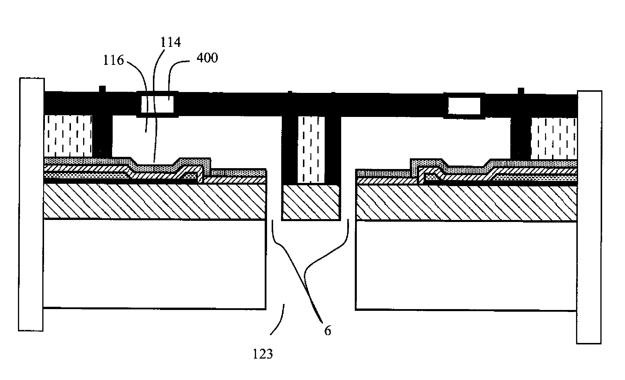
[0009]A preferred embodiment of the present invention is a nozzle for a drop ejector wherein the nozzle opening is shaped as a plurality of lobes adjoining a central opening region and extending along a radial direction away from the central region. Each lobe increases in width as distance from the central region increases. The nozzles have a small depth dimension and so include sidewalls that converge toward the central opening region of the nozzle, giving the lobe an optional teardrop shape. Because the central part of the nozzle opening is constricted the ink that is ejected pinches off in the center and provides several advantages. Such nozzles can be incorporated in inkjet printers that comprise arrays of multi-lobed nozzles.

Problems solved by technology

Thus satellite spots can cause printing defects including broadened vertical line width, fuzzy vertical line edges, and apparent jaggedness between portions of a vertical line that are printed by successive swaths printed in different directions.
However, with such a nozzle geometry, satellite caused defects are compounded when printing in the opposite direction.

Method used


Image

  • Drop ejector having multi-lobed nozzle
  • Drop ejector having multi-lobed nozzle
  • Drop ejector having multi-lobed nozzle

Examples


Embodiment Construction

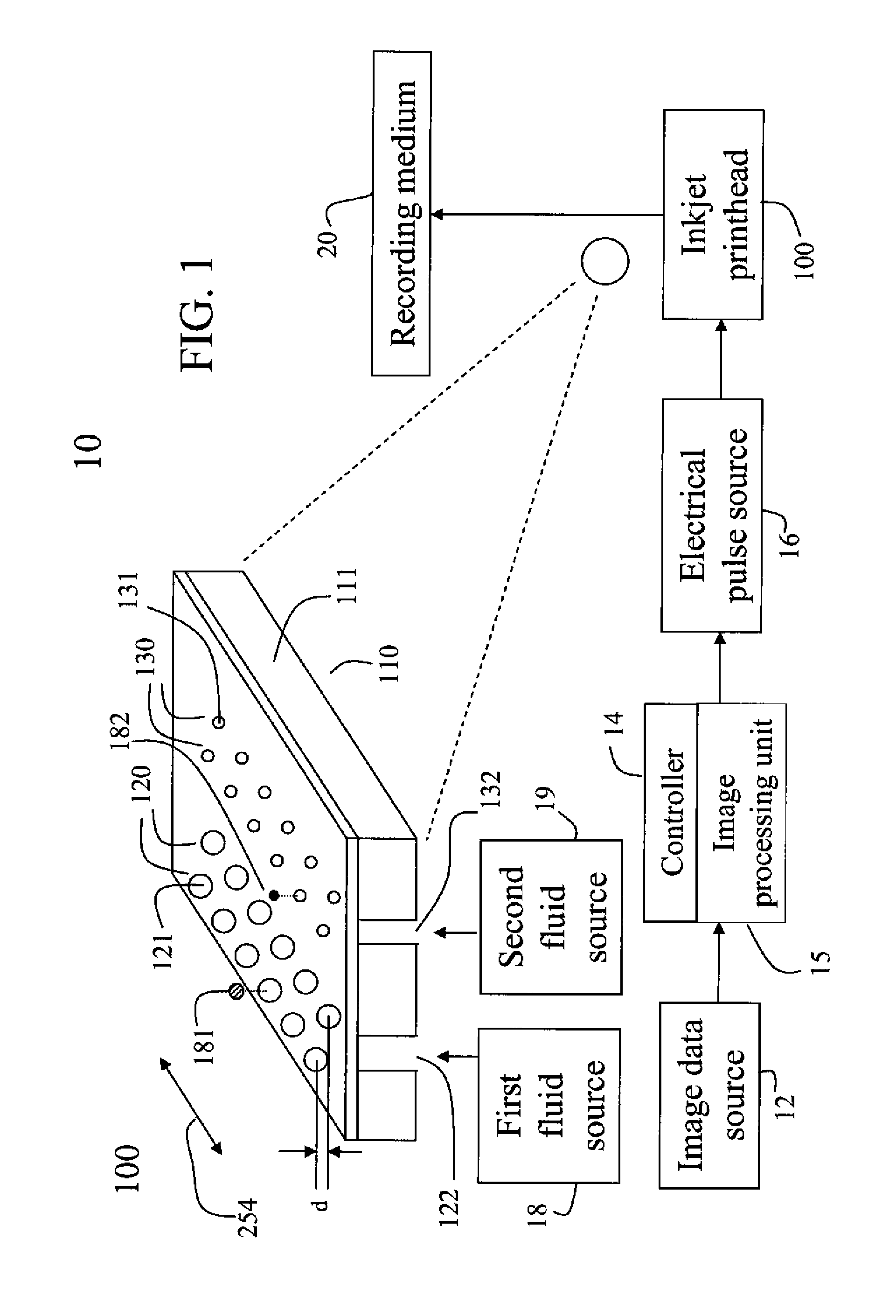
[0023]Referring to FIG. 1, a schematic representation of an inkjet printer system 10 is shown, for its usefulness with the present invention and is fully described in U.S. Pat. No. 7,350,902, which is incorporated by reference herein in its entirety. Inkjet printer system 10 includes an image data source 12, which provides data signals that are interpreted by a controller 14 as being commands to eject drops. Controller 14 includes an image processing unit 15 for rendering images for printing, and outputs signals to an electrical pulse source 16 of electrical energy pulses that are inputted to an inkjet printhead 100, which includes at least one inkjet printhead die 110.

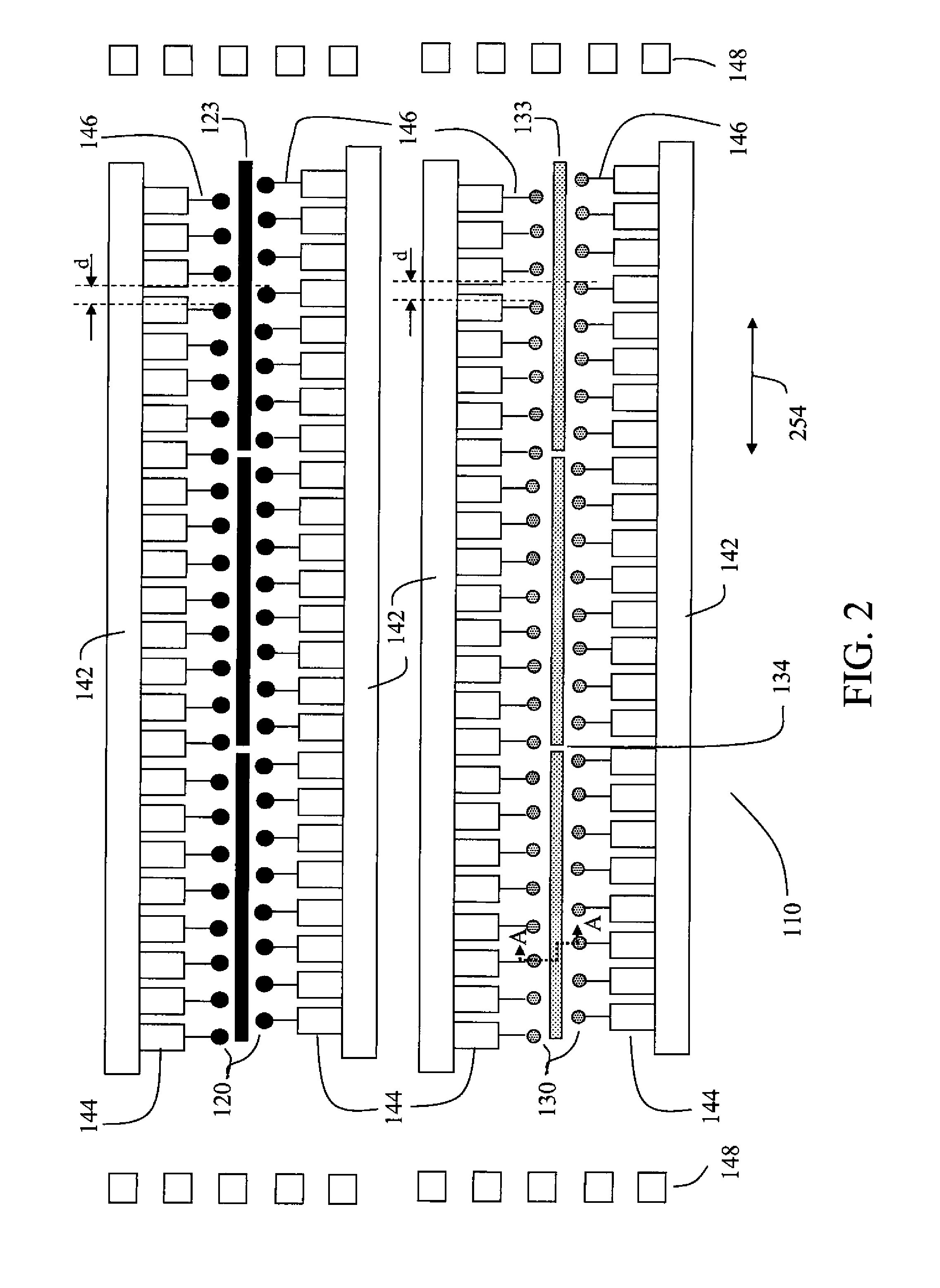
[0024]In the example shown in FIG. 1, there are two nozzle arrays 120 and 130 in the printhead that are each disposed along an array direction 254. Nozzles in the two nozzle arrays 120 and 130 are shown as circular in the generic example FIG. 1. Circular nozzles will serve as a comparative example for the multi-lobed ...


PUM


Abstract

A nozzle for a drop ejector is shaped as a plurality of lobes adjoining a central opening region and extending along a radial direction away from the central region. Each lobe increases in width as distance from the central region increases. The nozzles include sidewalls that converge toward the central opening region of the nozzle, giving the lobe a teardrop shape. Because the central part of the nozzle opening is constricted the ink that is ejected pinches off in the center and provides several advantages such as straighter trajectory, shorter tails, better accuracy, smaller ink volume, and less satellite effects.

Description

CROSS REFERENCE TO RELATED APPLICATIONS[0001]Reference is made to commonly assigned, co-pending U.S. Patent Applications:[0002]Ser. No. ______ by Yonglin Xie (Docket 95807) filed of even date herewith entitled “Method Of Making A Multi-Lobed Nozzle”; and[0003]Ser. No. ______ by Yonglin Xie (Docket 95808) filed of even date herewith entitled “Drop Ejection Method Through Multi-Lobed Nozzle”; the disclosures of which are incorporated herein by reference in their entireties.FIELD OF THE INVENTION[0004]This invention relates generally to the field of printing devices, and more particularly to the shape of a nozzle for drop ejector, for example for an inkjet printing device.BACKGROUND OF THE INVENTION[0005]Many types of printing systems include one or more printheads that have arrays of dot forming elements that are controlled to make marks of particular sizes, colors, or densities in particular locations on the recording medium in order to print the desired image. In some types of print...

Claims


Application Information

Patent Timeline
IPC IPC(8): B41J2/135
CPCB41J2/1404B41J2002/14475B41J2/1433
Inventor XIE, YONGLIN
Owner EASTMAN KODAK CO
Learn More