
Wall structure of building

a technology of building walls and walls, applied in the direction of walls, special buildings, parkings, etc., can solve the problems of uneven cutoff performance and inability to reduce component costs

Inactive Publication Date: 2002-02-21
YKK AP INC
View PDF0 Cites 4 Cited by
  • Summary
  • Abstract
  • Description
  • Claims
  • Application Information

AI Technical Summary

Benefits of technology

[0015] According to the present invention, since the cover member conceals, for instance, lower side of the mullion and transom, the inner batten itself may be sized to hold the facing member and may have smaller depth dimension than conventional arts. Further, since the cover member is independent of the inner batten, the cover member is not necessarily attached to a portion such as a spandrel portion of a curtain wall where even transom is not exposed. Accordingly, only the inner batten of smaller depth dimension is provided to the spandrel portion and a large cover member as compared to the inner batten is not required, so that production cost therefor can be reduced.
[0016] Further, since the depth dimension of the inner batten is reduced, the cutoff treatment between the mullion or the transom and the inner batten can be conducted after attaching the inner batten. In other words, since a space for attaching the cover member is formed on the indoor side of the inner batten, the seal material can be filled after attaching the inner batten using the space. The space can also be used for checking the condition after cutoff treatment, so that cutoff treatment may be conducted again when the condition is bad, thereby stabilizing cutoff performance.
[0019] However, in cutting the holding piece, the engaging portion of the post-attached outer batten provided on the indoor side of the holding piece can be simultaneously cut. It is strongly desired to eliminate such error during cutting work.
[0021] According to the above arrangement, when the holding piece is cut with, for instance, a hand tool such as a grinder, the engaging portion on the indoor side is not mistakenly cut by cutting along the mark. Accordingly, the holding piece can be easily and securely cut, thus improving workability.
[0024] On the other hand, according to the wall structure of a building of the present invention, since the thickness of the indoor seal member and the outdoor seal member, i.e. the pre-attached seal member and the post-attached seal member, is the same, the position of the facing member of the portion exchanging facing member thereof is consistent with the portion without exchanging the facing member in the depth direction, thereby improving appearance thereof.

Problems solved by technology

However, since the facing member cannot be always fitted from the indoor side when there is an obstacle such as a pillar on the indoor side, the outside glazing and the inside glazing may sometimes be combined in a single building.
Accordingly, if the inner batten having great depth is used in the spandrel portion without exposing the transom and the inner batten in the same manner as in the vision portion, the component cost cannot be reduced.
However, since the seal material is located on the backside of the inner batten after attaching the inner batten to the transom, the condition of cutoff treatment cannot be checked, so that cutoff performance can become uneven.
Further, even in vision portion, when an interior material such as casing and curtain box is disposed on immediately indoor side of the transom, since the inner batten is difficult to be detached on account of the interior material, the facing member has to be exchanged from the outdoor side.
However, since the pre-attached seal member is disposed on the indoor side and the post-attached seal member is fitted on the outdoor side when the facing member is exchanged from the outdoor side by cutting the holding piece of the mullion or the transom, thickness of the seal member on the indoor and the outdoor side is reversed relative to the other portion without exchanging the facing member, so that the position of the facing member in the depth direction becomes different to impair appearance thereof.

Method used


Image

  • Wall structure of building
  • Wall structure of building
  • Wall structure of building

Examples


Embodiment Construction

)

[0032] An embodiment of the present invention will be described below with reference to attached drawings.

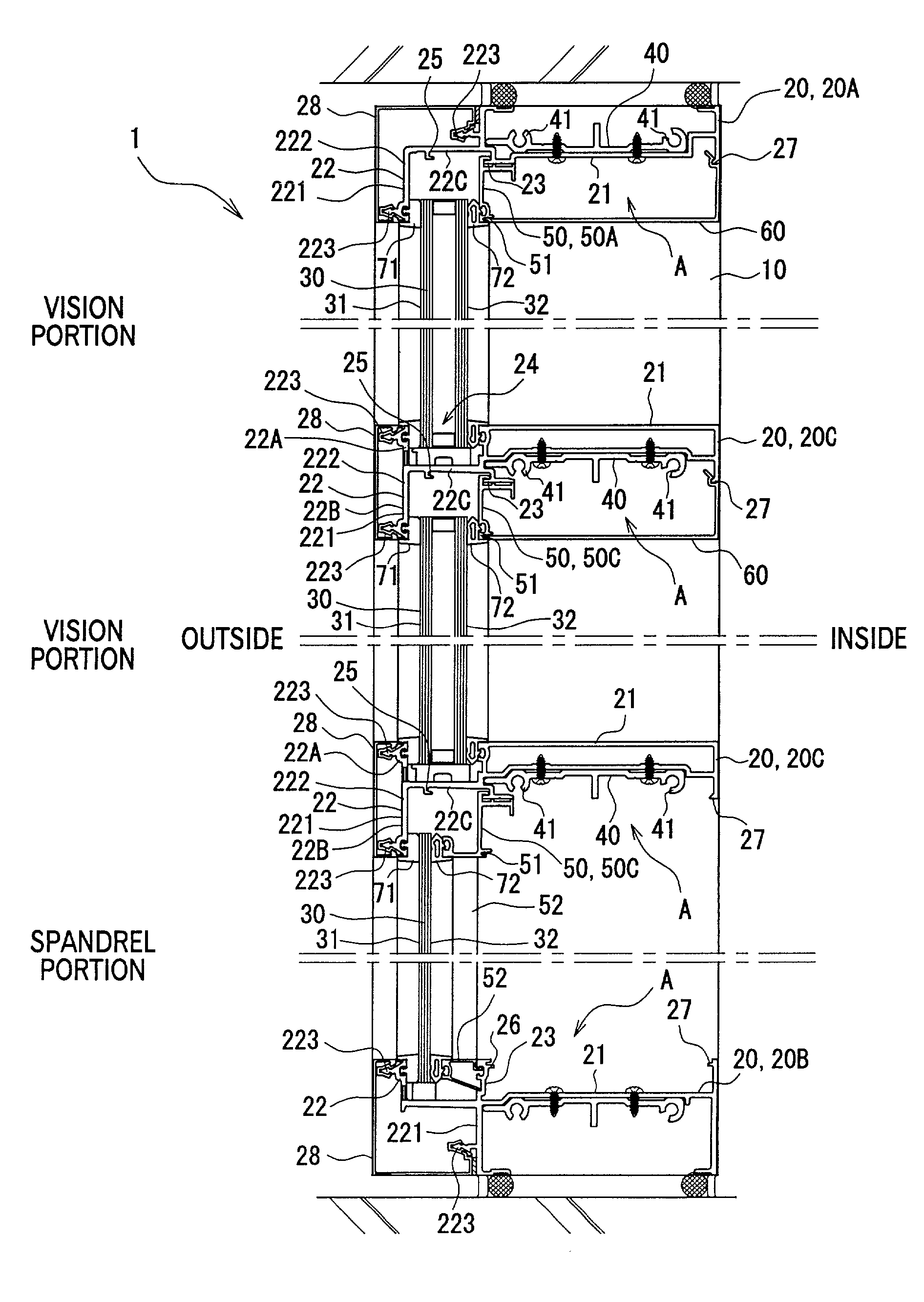
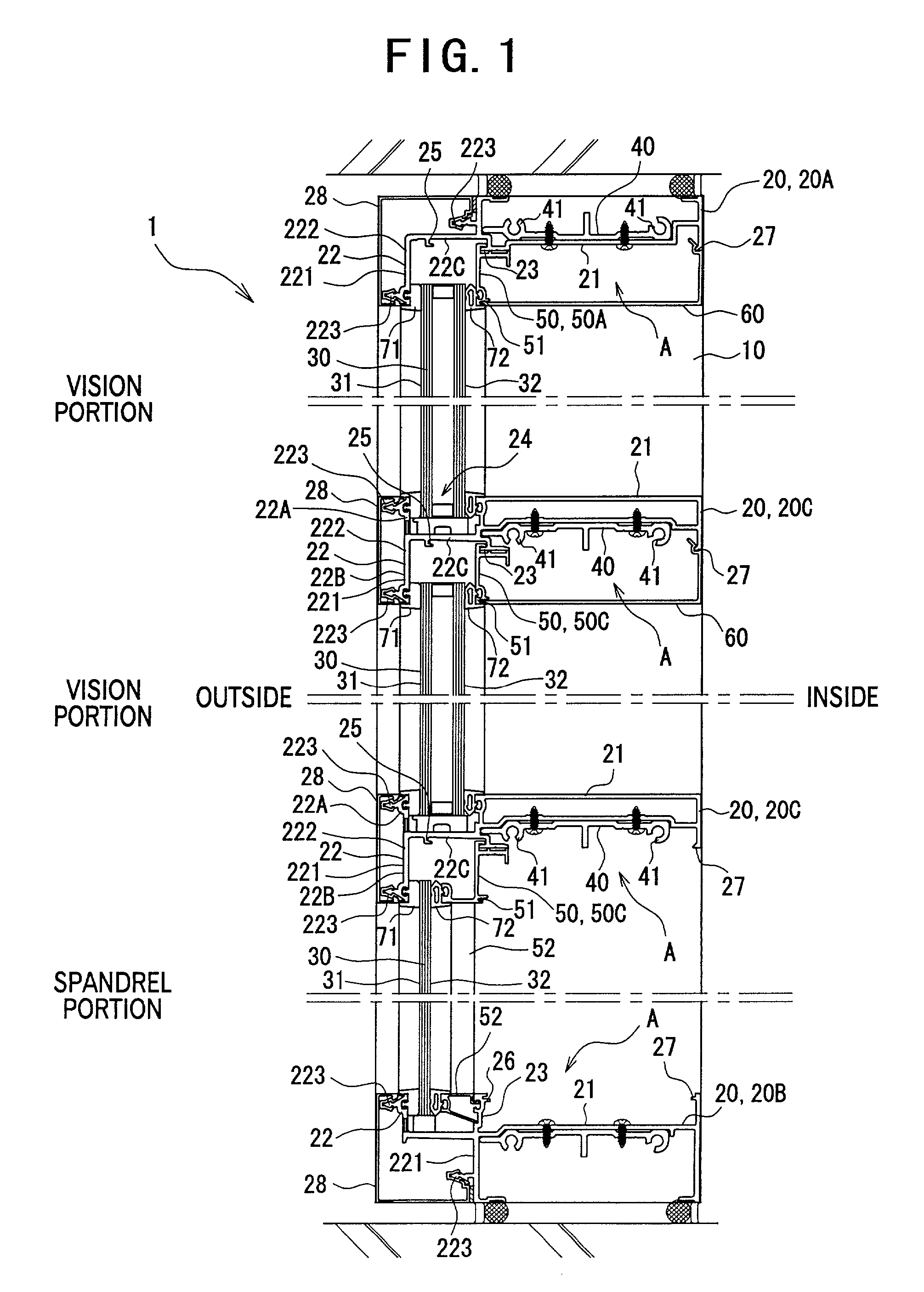
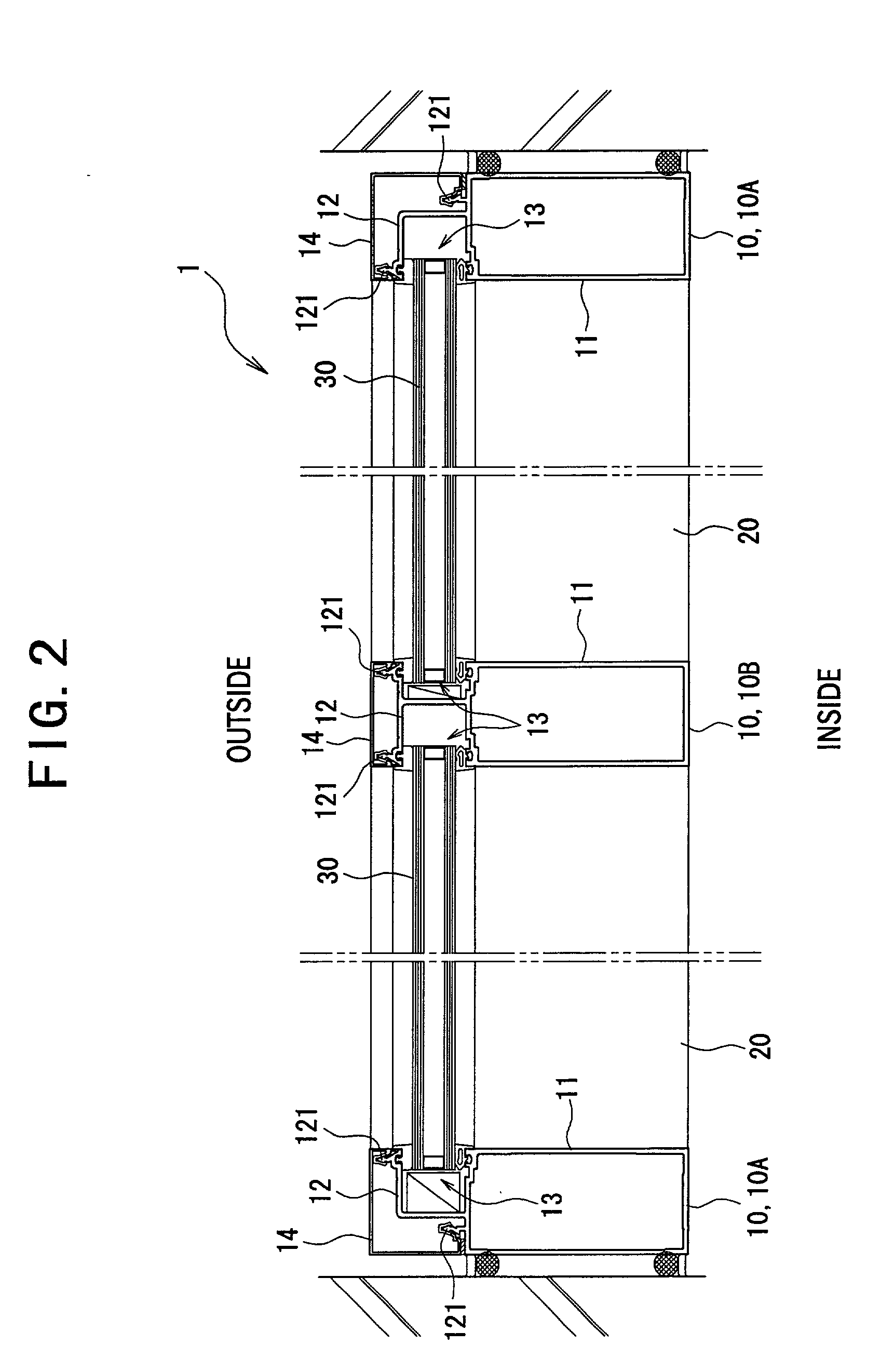
[0033] FIG. 1 is a vertical cross section showing a curtain wall applied with a wall structure according to the present embodiment, and FIG. 2 is a horizontal cross section of the curtain wall 1.

[0034] The curtain wall 1 has a plurality of vertical mullions 10 spaced apart with each other, a plurality of horizontal transoms 20 extending between the mullions 10 vertically spaced apart with each other, a facing member disposed in a section formed by the right and left mullions 10 and the upper and lower transoms 20, i.e. single-glazing or double-glazing glass plate 30. The curtain wall 1 is a knockdown type formed by the mullions 10, the transoms 20 and the glass plates 30 independently carried to a construction site, and is an inside-glazing type in which the glass plate 30 is fitted from the indoor side.

[0035] As shown in FIG. 2, the mullion 10 includes a mullion 10A vertically...


PUM


Abstract

Depth of an inner batten (50C) is reduced and an indoor space (A) is covered with a cover member (60), so that, though the cover member (60) is attached to conceal a lower side of a transom (20C) from an indoor side in a vision portion, the cover member (60) can be omitted in a spandrel portion where the lower side of the transom (20C) cannot be seen in order to reduce production cost, and, even after the inner batten (50C) is attached to the transom (20C), cutoff treatment can be easily conducted before attaching the cover member (60), thereby obtaining stable cutoff performance by checking coating condition of a sealing material (90).

Description

[0001] 1. Field of the Invention[0002] The present invention relates to a wall structure of a building, which can be suitably used for a knockdown-type curtain wall of which mullions, transoms, facing members, battens etc. are independently transferred to a construction sites to form exterior wall.[0003] 2. Description of Related Art[0004] Conventionally, following two methods are known for constructing facing members such as glass plate and aluminum panel in the above knockdown-type curtain wall.[0005] One method is outside glazing for fitting the facing member to a section formed by mullions and transoms from the outdoor side. The other is inside glazing for fitting the facing member from the indoor side.[0006] The inside glazing is mainly used for a building where a scaffold is difficult to be set up. However, since the facing member cannot be always fitted from the indoor side when there is an obstacle such as a pillar on the indoor side, the outside glazing and the inside glazi...

Claims


Application Information

Patent Timeline
IPC IPC(8): E04B2/74E04B1/66E04B2/96
CPCE04B2/7455
Inventor ISHIKAWA, MASAYOSHITAKEMURA, MASAMITAKAHASHI, TSUTOMU
Owner YKK AP INC
Learn More