Radio terminal and radio communication method

a radio terminal and radio communication technology, applied in the direction of network topologies, electrical equipment, connection management, etc., can solve the problems of radio terminal and radio base station not being radio terminal and radio base station cannot communicate and not always able to continue direct communication with the radio base station

Inactive Publication Date: 2011-02-24
KYOCERA CORP
View PDF4 Cites 16 Cited by
  • Summary
  • Abstract
  • Description
  • Claims
  • Application Information

AI Technical Summary

Benefits of technology

[0013]A fifth characteristic of the present invention is summarized as the radio communication terminal according to any one of the first to fourth characteristics, further comprising: a reception quality measurement unit (communication judgment unit 131) configured to measure a reception quality, which is a quality of a radio signal received from the radio base station; and a threshold comparison unit (communication judgment unit 131) configured to compare the reception quality measured by the reception quality measurement unit, with a threshold, wherein the continuation judgment unit judges that the direct communication with the radio base station is not possible to continue, when the reception quality is below the threshold.

Problems solved by technology

In the above-described tree structure network, the root radio terminal is not always capable of continuing the direct communication with the radio base station.
For example, the technique has a problem that, when the root radio terminal moves outside the radio wave reachable range of the radio base station, the radio terminal and the radio base station cannot continue the direct communication.
In addition, the technique has a problem that, when the root radio terminal cannot continue a direct communication, the lower-level radio terminal communicating with the radio base station via the root radio terminal and being outside the radio wave reachable range cannot communicate with the radio base station.

Method used


Image

  • Radio terminal and radio communication method
  • Radio terminal and radio communication method
  • Radio terminal and radio communication method

Examples


Embodiment Construction

of the master / slave reversing operation according to the embodiment of the present invention.

[0031]FIG. 7 is a view for describing Operation Example 2 of the master / slave reversing operation according to the embodiment of the present invention.

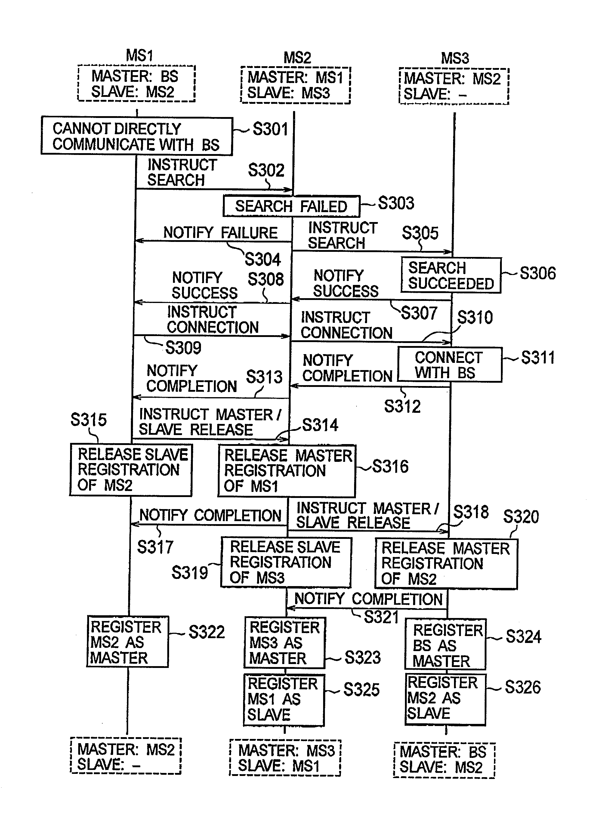
[0032]FIG. 8 is a sequence diagram showing Operation Example 2 of the master / slave reversing operation according to the embodiment of the present invention.

BEST MODES FOR CARRYING OUT THE INVENTION

[0033]Next, an embodiment of the present invention is described with reference to the drawings. Specifically, description is given of (1) a schematic configuration of an entire radio communication system, (2) a configuration of a radio terminal, (3) operation of the radio terminal, (4) operations and effects, and (5) other embodiments.

[0034]It is to be noted that the same or similar reference numerals are attached to the same or similar elements in the following description of the embodiment.

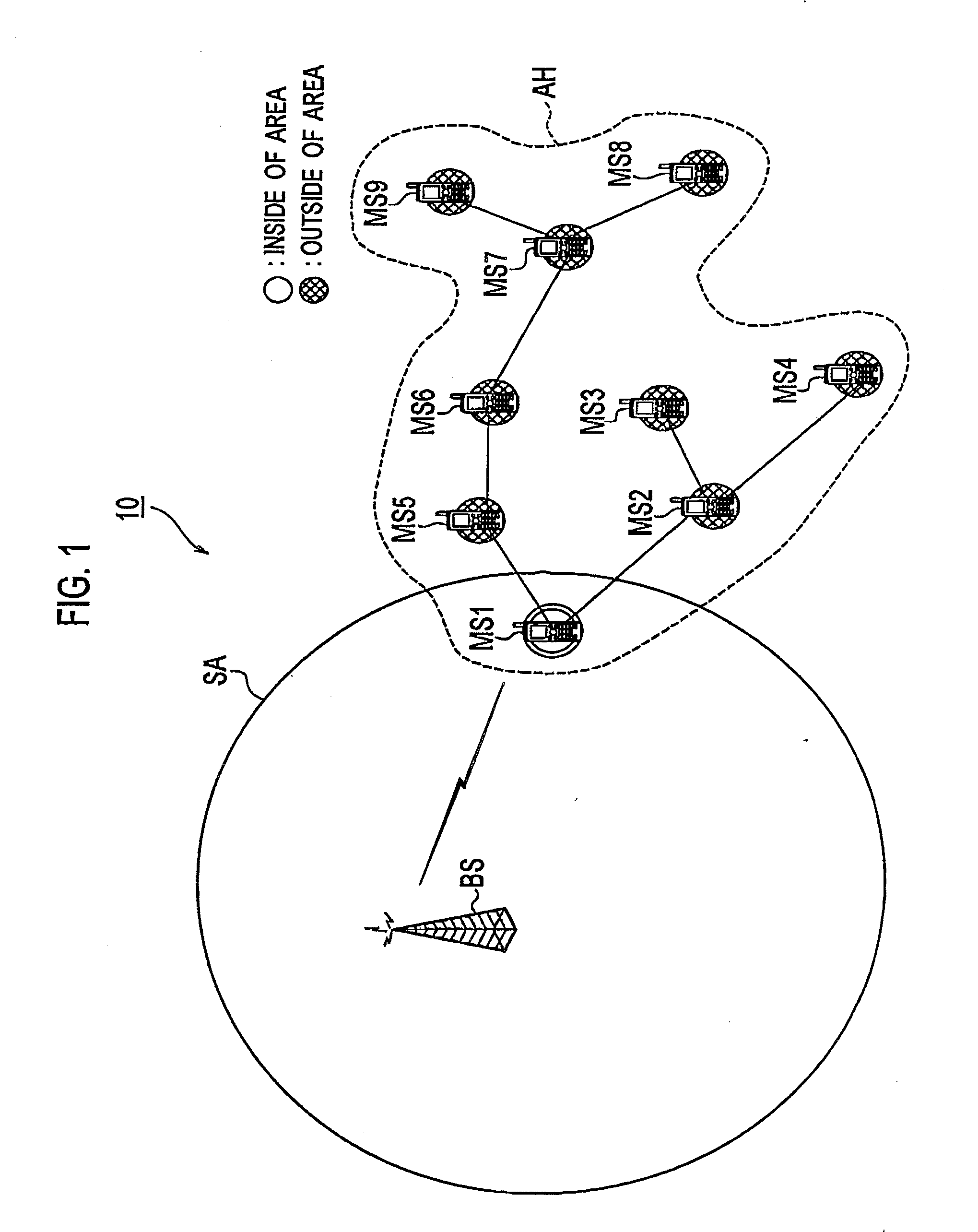
[0035](1) Schematic Configuration of Entire Radio Communica...


PUM


Abstract

A radio terminal according to a present invention comprising a communication judgment unit (131) configured to judge whether or not the direct communication with the radio base station is possible to continue; a message processor (132) configured to transmit an inquiry message inquiring whether or not a direct communication with the radio base station is possible, to a lower-level radio terminal in the tree structure network, when the continuation judgment unit judges that the direct communication with the radio base station is not possible to continue; and a master manager configured to register the lower-level radio terminal as an upper-level radio terminal in the tree structure network, upon receipt of a response message indicating that a direct communication with the radio base station is possible, from the lower-level radio terminal.

Description

TECHNICAL FIELD[0001]The present invention relates to: a radio terminal forming to a tree structure network in which a radio terminal directly communicating with a radio base station is set to be a root radio terminal; and a radio communication method used by the radio terminal.BACKGROUND ART[0002]An ad hoc network has conventionally been known, which is a radio network autonomously configured by multiple radio terminals each having a relay function. Meanwhile, a technique by which a radio terminal forming an ad hoc network communicates with a radio base station has been proposed (see Patent Document 1, for example). Specifically, the radio terminal communicates with the radio base station via a different radio terminal.[0003]To be more specific, a tree structure network is formed of multiple radio terminals, and has a radio terminal directly communicating with a radio base station, as a root. A lower-level radio terminal is configured to communicate with the radio base station via ...

Claims


Application Information

Patent Timeline
Patent Type & Authority Applications(United States)
IPC IPC(8): H04W24/02
CPCH04W84/18H04W40/24H04W76/14H04W48/16H04W40/246H04W60/04H04W88/04
Inventor HIDAKA, HIROYUKI
Owner KYOCERA CORP
Why Eureka
Try Eureka