Gas sparger for an immersed membrane

a technology of gas sparger and immersed membrane, which is applied in the direction of membranes, carburetizing air, separation processes, etc., can solve the problems of producing undesirable pressure spikes and large bubbles

Active Publication Date: 2011-03-03
BL TECH INC
View PDF34 Cites 83 Cited by
  • Summary
  • Abstract
  • Description
  • Claims
  • Application Information

AI Technical Summary

Problems solved by technology

However, it was also noted in WO/2000/021890 that creating these large bub

Method used


Image

  • Gas sparger for an immersed membrane
  • Gas sparger for an immersed membrane
  • Gas sparger for an immersed membrane

Examples


Embodiment Construction

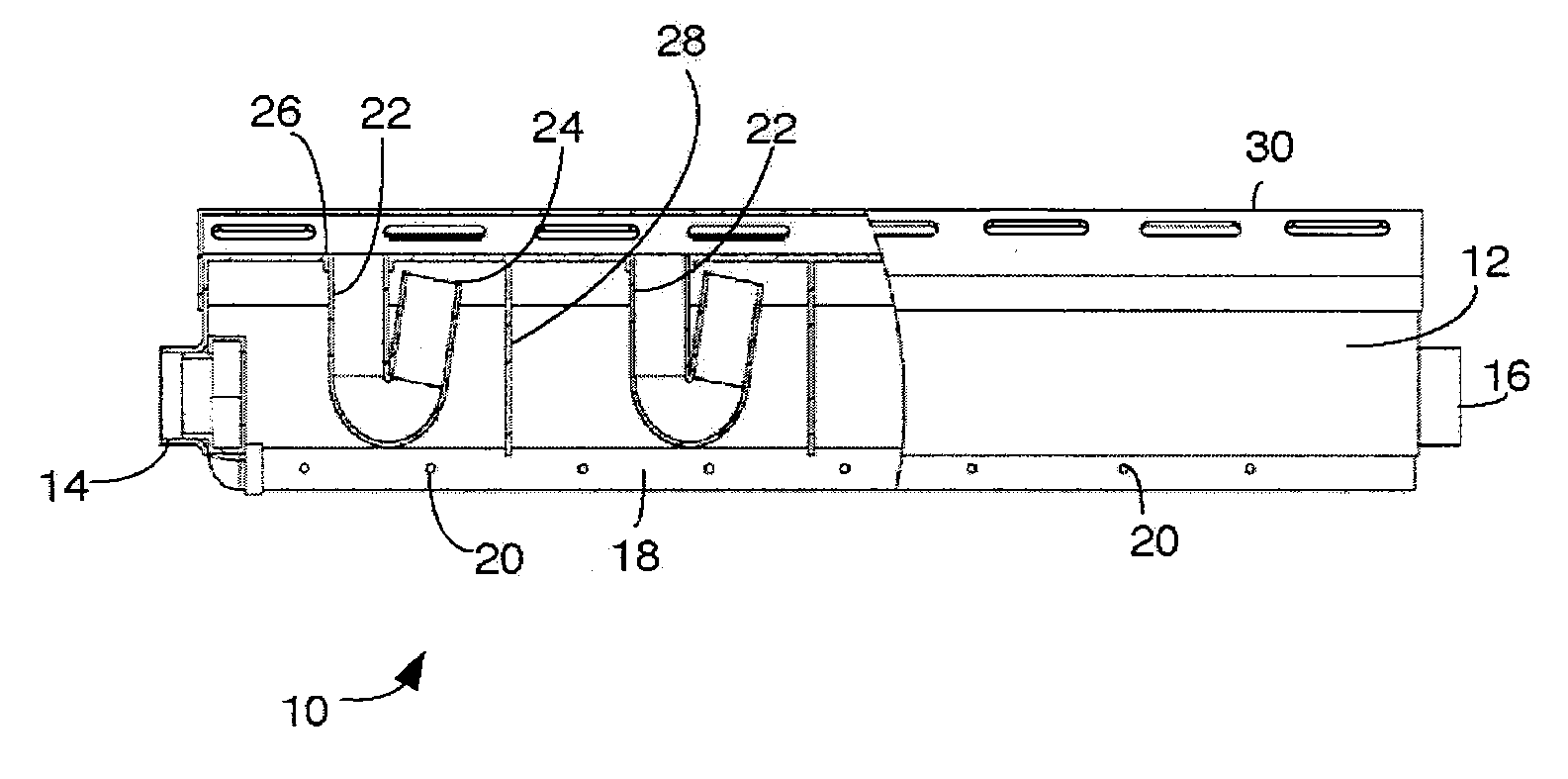
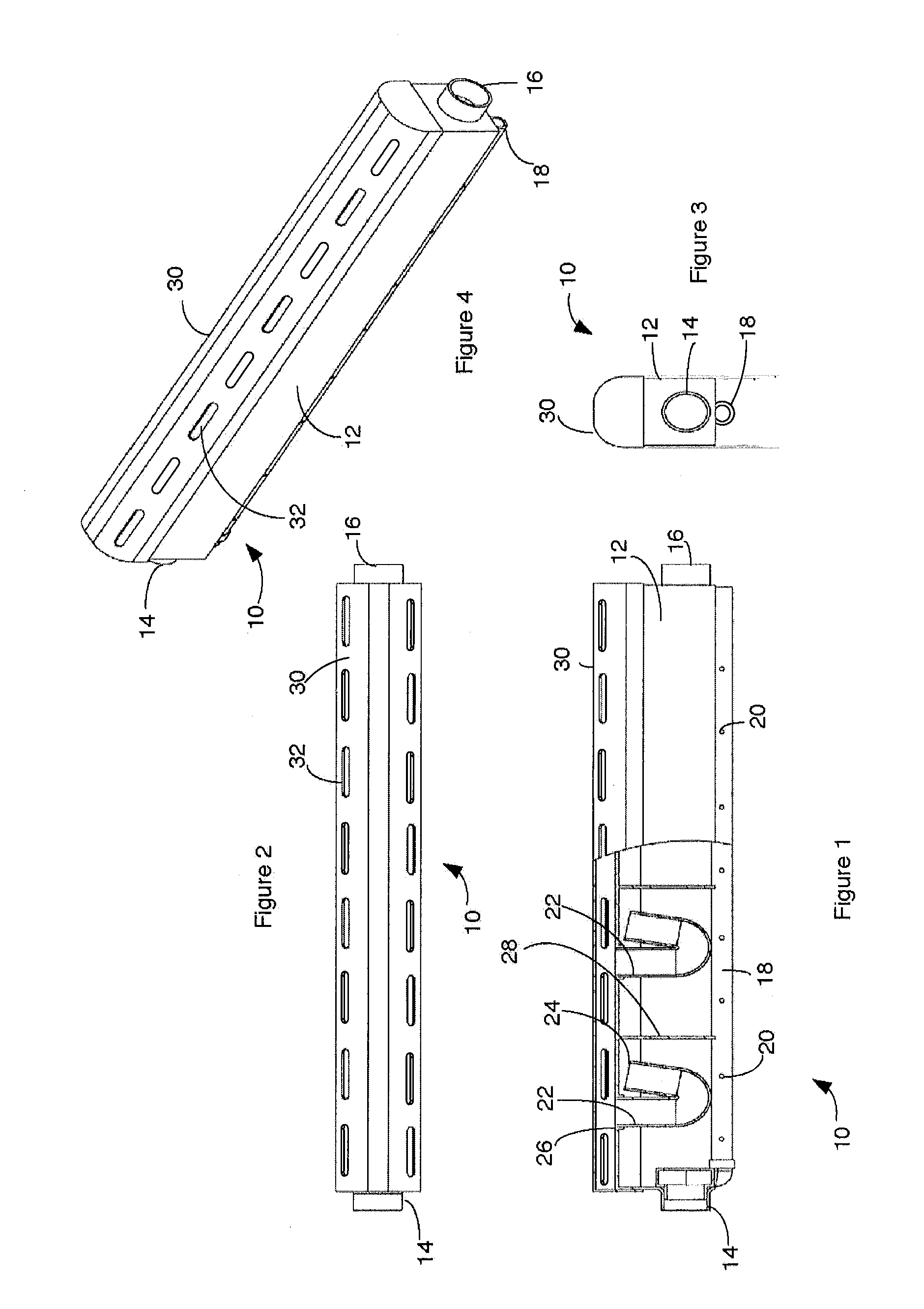
[0012]FIGS. 1 to 4 show a sparger 10 in various views. Sparger 10 has a housing 12 defining an interior chamber bounded by an upper surface. The housing 12 shown is elongated, with its length being more than twice its width, and has a generally inverted “U” cross section, although other shapes may also be used. The housing 12 shown has a connection 14 at one end. Connection 14 can be fit into or over a port in a gas supply manifold (not shown) to provide gas to the sparger 10 and to hold one end of the sparger 10 in a selected position immersed in a liquid. The other end of the sparger 10 may be held in a selected position immersed in a liquid by a pin 16 extending from the housing 12.

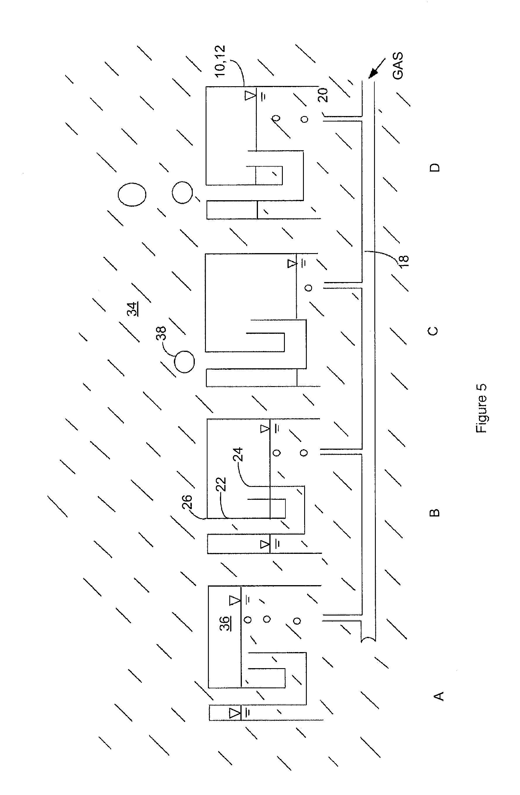
[0013]The connector 14 is connected to one or more distribution pipes 18. Distribution pipes 18 extend generally along the length of the sparger 10 and have gas outlets 20 along their length. The size of the gas outlets 20 may be made sufficiently small relative to the gas flow rate so as to (a) create...


PUM

PropertyMeasurementUnit
Timeaaaaaaaaaa
Timeaaaaaaaaaa
Areaaaaaaaaaaa

Abstract

A gas sparger produces an intermittent flow of bubbles even if provided with a continuous gas flow. The sparger has a housing to collect a pocket of gas and a conduit to release some of the gas from the pocket when the pocket reaches a sufficient size. Optionally, a cover over an outlet from the conduit may break up or distribute the released gas. A large sparger for use with a commercial membrane module can comprise a plurality of smaller units.

Description

FIELD[0001]This specification relates to a gas sparger and to gas scouring to inhibit fouling of an immersed membrane.BACKGROUND[0002]The following background discussion is not an admission that anything discussed below is citable as prior art or common general knowledge.[0003]International PCT publication WO / 2000 / 021890 describes an aeration system for a submerged membrane module that has a set of aerators connected to an air blower, valves and a controller adapted to alternately provide a higher rate of air flow and a lower rate of air flow in repeated cycles to individual aerators. In an embodiment, the air blower, valves and controller, simultaneously provide alternating air flows to two or more sets of aerators such that while the total system air flow is constant, allowing the blower to be operated at a constant speed, each aerator receives a flow of air that varies over time. In some embodiments, the flow of air to an aerator occurs in repeated cycles of short duration. Trans...

Claims


Application Information

Patent Timeline
IPC IPC(8): B01D65/08B01F3/04B01D69/00
CPCB01D61/08B01D61/18B01D65/00B01D65/02B01D65/08B01F2003/04304B01D2315/06B01D2321/185B01D2321/26B01F3/04241B01D2313/26B01F23/2312B01F23/231263Y02W10/10B01D61/00C02F1/44B01D61/22B01D61/12B01F23/23123B01F23/231265
Inventor CUMIN, JEFFBEHMANN, HENRYHONG, YOUNGSECKBAYLY, REID
Owner BL TECH INC
Why Eureka
Try Eureka