Hemostasis valve with iris seal

a technology of iris seal and hemostasis valve, which is applied in the field of medical devices and methods, can solve problems such as the tendency to leak fluid when not desired

Active Publication Date: 2011-03-03
PACESETTER INC
View PDF6 Cites 58 Cited by
  • Summary
  • Abstract
  • Description
  • Claims
  • Application Information

AI Technical Summary

Problems solved by technology

Unfortunately, hemostasis valves known in the art to provide acceptable sealing capability for a range of sizes that is not inconsequential often r...

Method used


Image

  • Hemostasis valve with iris seal
  • Hemostasis valve with iris seal
  • Hemostasis valve with iris seal

Examples


Embodiment Construction

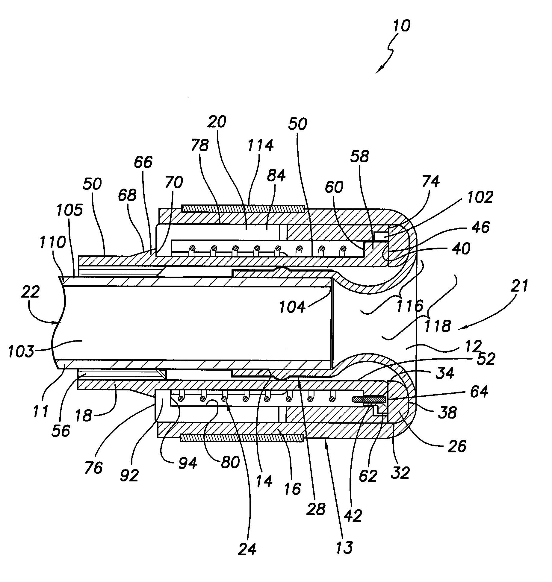
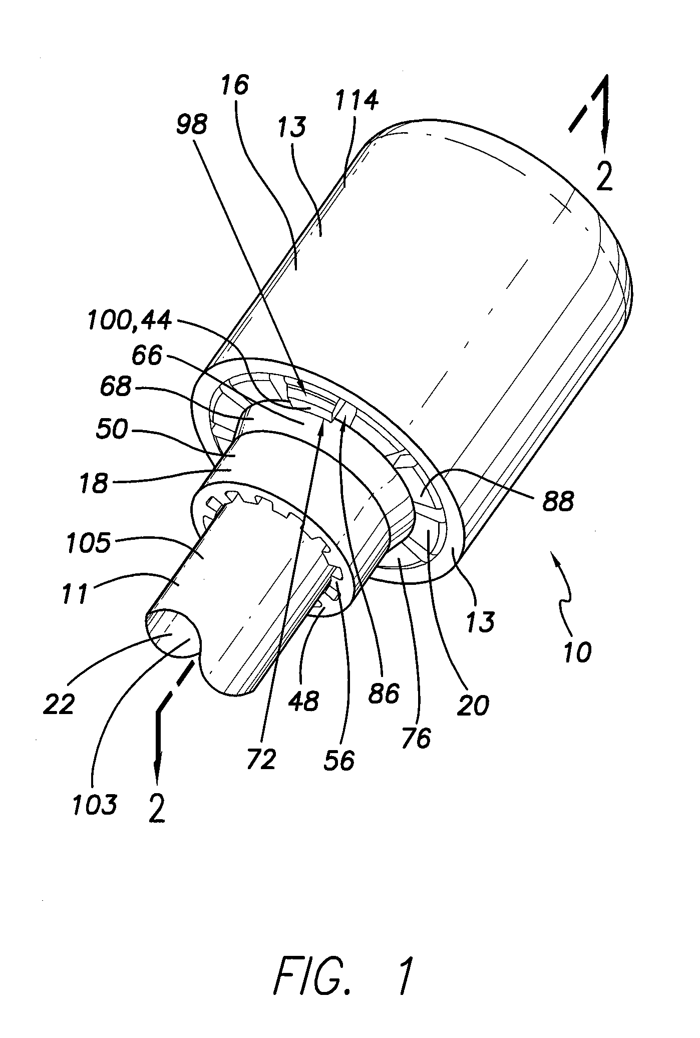
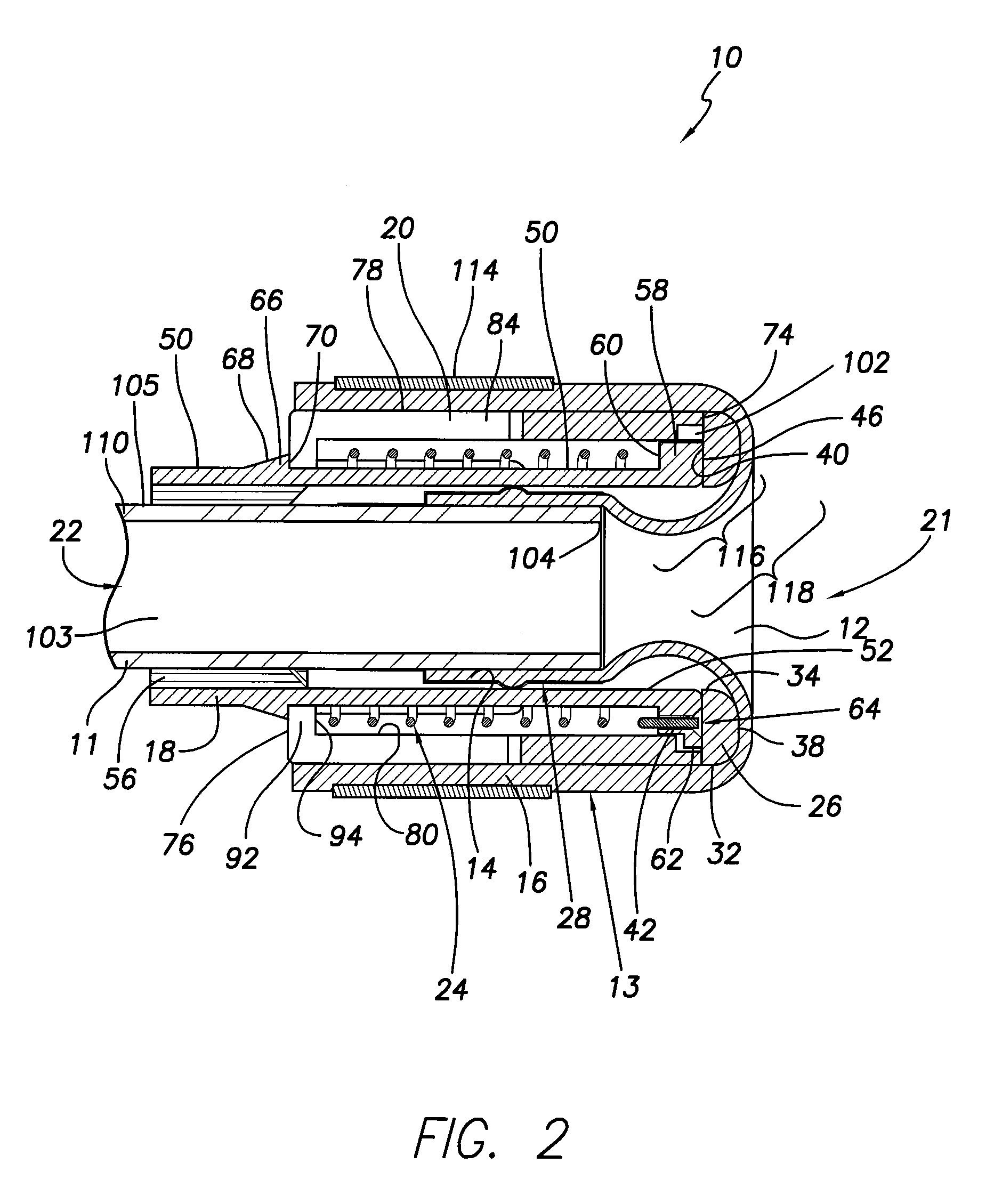
[0019]A hemostasis valve 10 is disclosed herein for use with a sheath or catheter 11 employed in a minimally invasive medical procedure, for example, in the delivery of an implantable electrotherapy lead. In one embodiment, the hemostasis valve 10 includes an iris valve 12 formed of an elastomeric membrane 13 having an inner end 14 and an outer end 16 respectively coupled to an inner bushing 18 and a rotation sleeve 20. The rotation sleeve 20 may be rotated relative to the inner bushing 18 to cause the iris valve 12 to transition between a fully closed state and a fully open state, thereby sealing or opening a proximal opening 21 of the hemostasis valve 10, the opening 21 providing access to the proximal end of the catheter lumen 22. In one embodiment, the hemostasis valve 10 may include a biasing feature 24 that causes the iris valve 12 to be biased to assume the closed state.

[0020]For a detailed discussion regarding the hemostasis valve 10, reference is made to FIGS. 1-3, which ar...


PUM


Abstract

A hemostasis valve is disclosed herein. The hemostasis valve may include an inner bushing, a rotation sleeve, an elastomeric sleeve, and a biasing element. The rotation sleeve may extend about the inner bushing and be rotationally displaceable relative to the inner bushing. The elastomeric sleeve may include a first end operably coupled to the inner bushing, a second end operably coupled to the rotation sleeve, and an iris valve portion. Rotation of the rotation sleeve relative to the inner bushing may cause the iris valve to transition from an open state to a closed state. The biasing element may act between the rotation sleeve and inner bushing to bias the iris valve towards at least one of a closed state or an open state.

Description

FIELD OF THE INVENTION[0001]The present invention relates to medical apparatus and methods. More specifically, the present invention relates to hemostasis valves and methods of using and manufacturing such valves.BACKGROUND OF THE INVENTION[0002]Hemostasis valves are employed in minimally invasive medical procedures such as, for example, the implantation of electrotherapy leads. Depending on the type of minimally invasive procedure occurring, the hemostasis valve may need to accommodate devices having a variety of diameters.[0003]Unfortunately, hemostasis valves known in the art to provide acceptable sealing capability for a range of sizes that is not inconsequential often require two hands to operate. Also, such known hemostasis valves are biased to assume the open state, leading to a tendency to leak fluid when not desired.[0004]There is a need in the art for a hemostasis valve that provides adequate sealing capabilities over a wide range of diameters for the devices that may be e...

Claims


Application Information

Patent Timeline
IPC IPC(8): A61B17/34
CPCA61B17/3439A61M39/0613A61B17/3462
Inventor WHITING, JAMES S.HAFELFINGER, WERNEREIGLER, NEAL L.WARDLE, JOHN L.
Owner PACESETTER INC
Why Eureka
Try Eureka