Eureka AIR delivers breakthrough ideas for toughest innovation challenges, trusted by R&D personnel around the world.

Flexible grip die-alignment arrangement

Inactive Publication Date: 2011-03-24
GREENLEAF RICHARD J
View PDF11 Cites 28 Cited by
  • Summary
  • Abstract
  • Description
  • Claims
  • Application Information

AI Technical Summary

Benefits of technology

[0017]A threaded bore is arranged through the side edge of the exemplary center punch holder plate and extends up to the radially outer surface of that generally semi circular cut, meeting the cut at a location of about one third the distance from the distal end of that cut. An adjustment bolt is disposed within that threaded bore so as to effect (or release) a bias on the radially outward side of the cut, when that adjustment bolt is rotated within that bore. That generally semicircular cut through the exemplary center punch holder plate in effect creates a “flexible grip” finger. A bias inwardly by the adjustment bolt against the finger presses a semi-circular curved wall portion of that finger slightly inwardly radially, so as to distort the irregular bore and hence create a perfect circular hole in that central bore. When for example, a tool such as a center punch is placed within the center punch holder plate, and the adjustment bolt is tightened with respect to that finger, the center punch is now

Problems solved by technology

That in turn establishes inaccuracies and a loss of concentricity of the alignment of those tools.

Method used


Image

  • Flexible grip die-alignment arrangement
  • Flexible grip die-alignment arrangement
  • Flexible grip die-alignment arrangement

Examples


Embodiment Construction

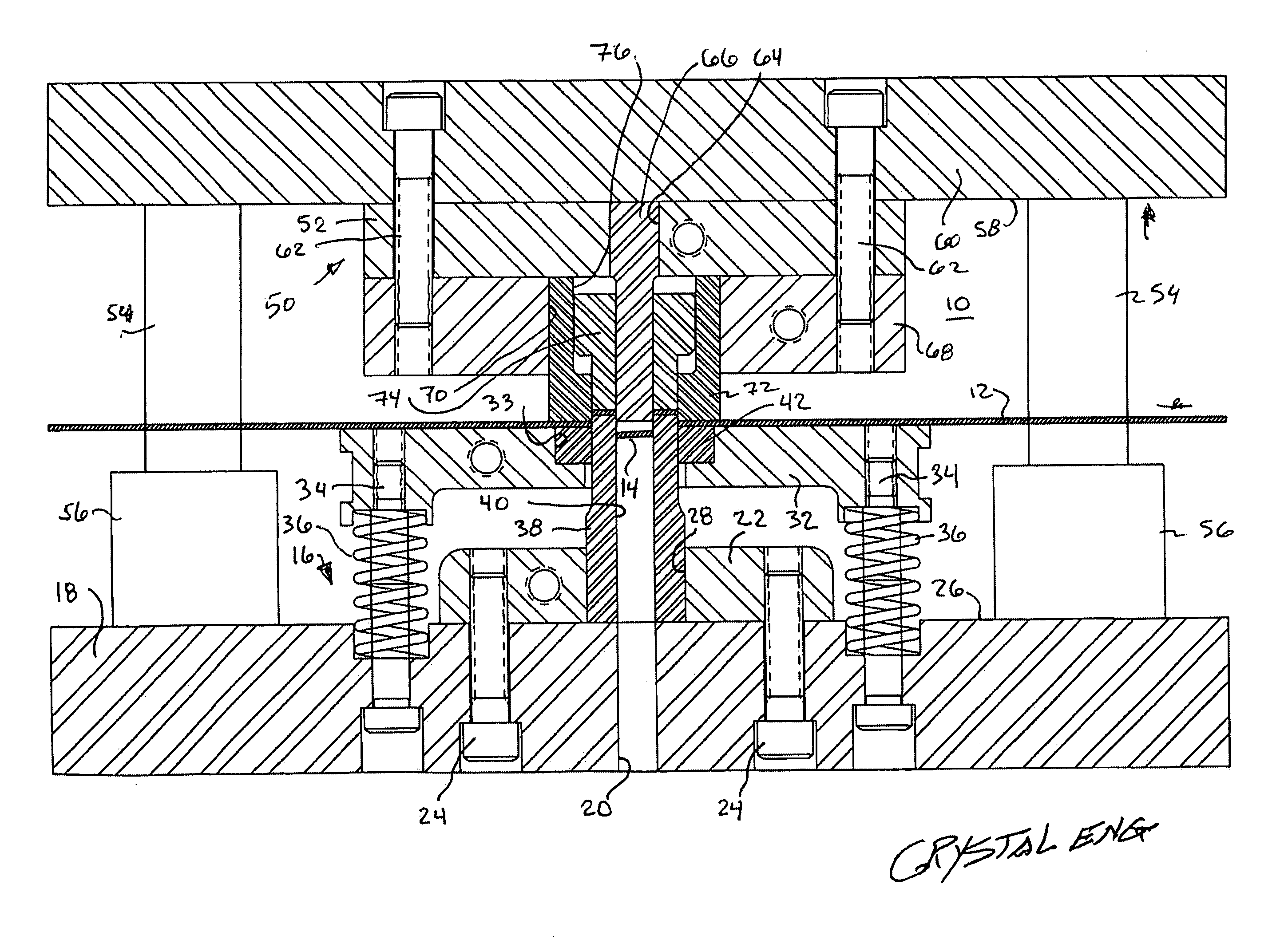
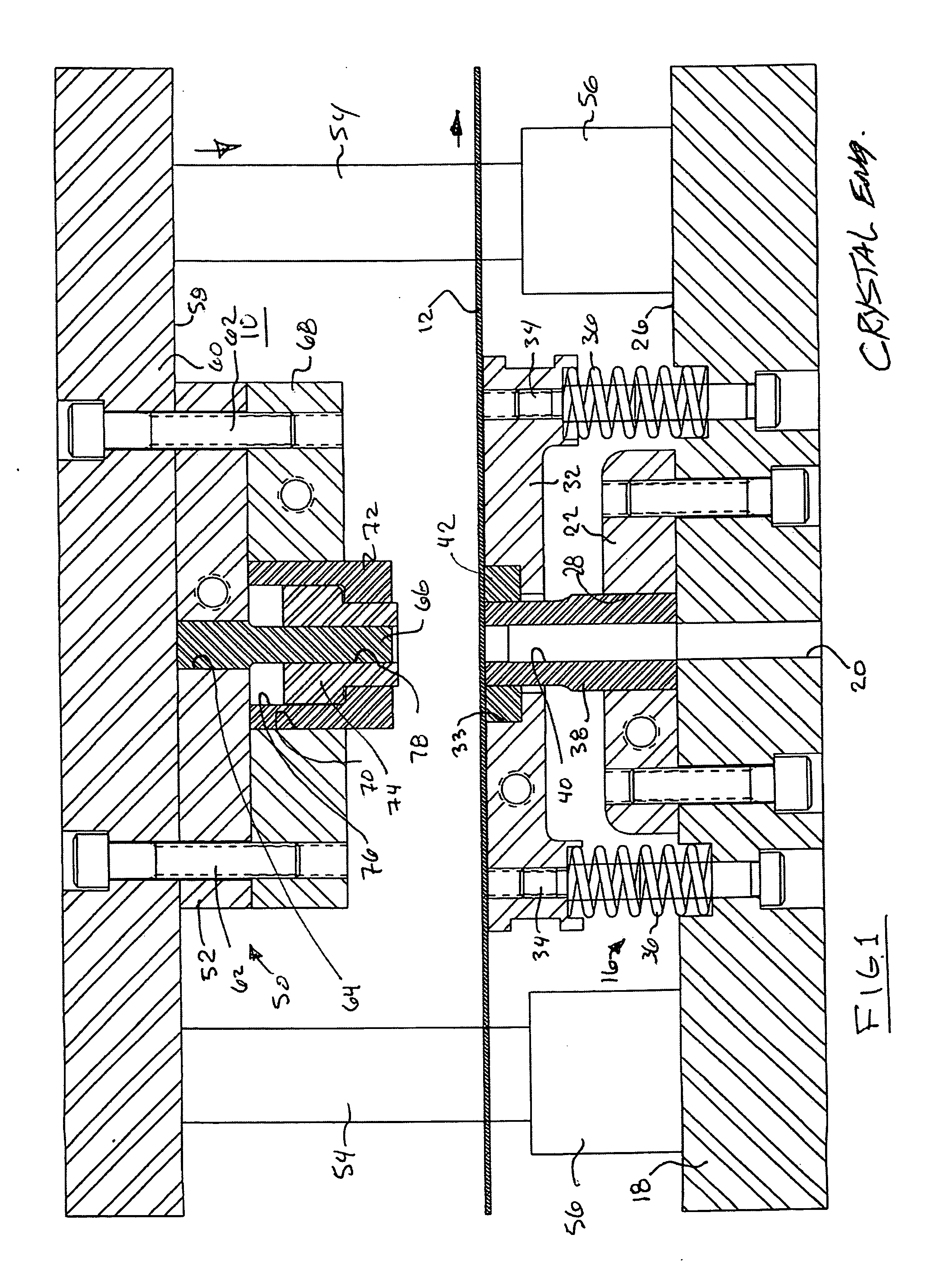
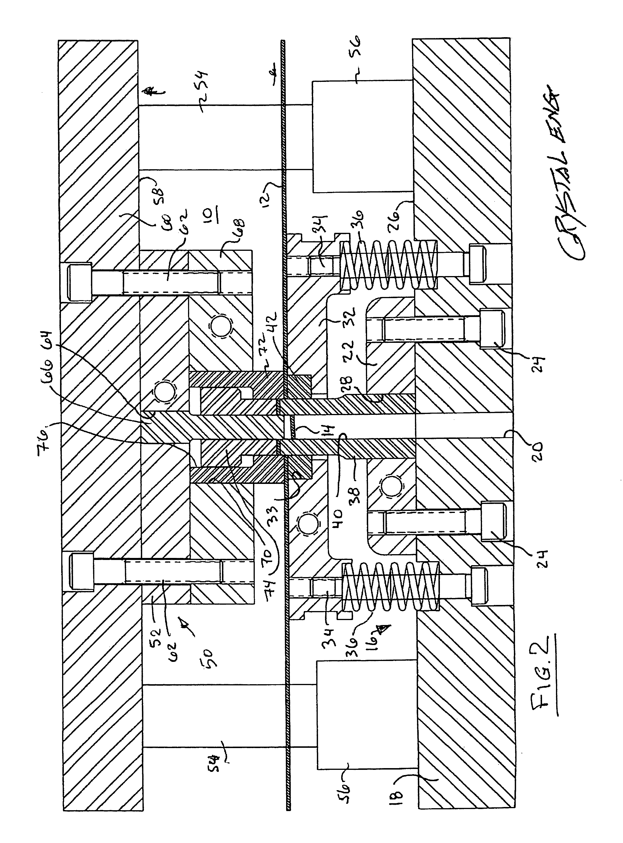
[0027]Referring now to the drawings in detail and particularly to FIGS. 1 and 2, there is shown the present invention which comprises a die set assembly or arrangement 10 for the manufacture of punched parts from a traveling web or sheet of material 12 such as metal or plastic to produce washers 14 or the like.

[0028]The die set assembly or arrangement 10 of the present invention comprises a base portion 16 which comprises a lowermost die shoe 18. The lowermost die shoe 18 has a central bore 20 of a first diameter D1, extending therethrough. A compound punch holder plate 22 is attached, by an arrangement of bolts 24, to the upper side 26 of the die shoe 18 and has a central bore 28 extending therethrough, of a second diameter D2. A stripper holder plate 32 is reciprocably supported on an arrangement of shoulder screws 34 arranged between the lowermost die shoe 18 and the stripper holder plate 32 itself. Die springs 36 compressibly support the stripper holder plate 32 over the compoun...


PUM

PropertyMeasurementUnit
Angleaaaaaaaaaa
Circumferenceaaaaaaaaaa

Abstract

A die press assembly for producing punched parts from a travelling web of material, the die press comprising: a lower die shoe securing a compound punch holder plate thereon, the compound punch holder biasedly gripping a compound punch tool therein, the lower die shoe also supporting a reciprocably movable stripper holder plate, wherein the compound punch extends slideably through a biasedly gripped stripper holder tool in the stripper holder plate; an upper punch holder movable with respect to the lower die shoe, the upper punch holder having a center punch holder plate which biasedly grips a center punch tool therewithin; and a die holder plate fixedly attached to the center punch holder plate with a biasedly gripped die tool slideably enclosing the center punch, wherein each of the biasedly gripped tools are in co-axial alignment in distortable bores in their respective plates.

Description

[0001]This invention relates to punch press assemblies and more particularly to tool-holding grip arrangements for gripping tools to permit very accurate alignment arrangements to facilitate the alignment of opposing tools utilized to pierce a sheet of material such as for example in a punch press, and is a continuation-in-part of co-pending application Ser. Nos.: 12 / 214,924 filed Jun. 24, 2008 and 11 / 450,526 filed Jun. 9, 2006, each incorporated herein by reference in their entirety.BACKGROUND OF THE INVENTION[0002]1. Field of the Invention[0003]2. Discussion of the Prior Art[0004]Compound tooling is currently utilized by hundreds of manufacturers to produce thousands of different types of washers made from aluminum, brass, copper, nylon, steel utilized in almost everything society touches. Washers are for example, utilized in any product with nuts and bolts or moving parts. The inside diameter and the outside diameter of these washers or other punched parts have become more critic...

Claims


Application Information

Patent Timeline
IPC IPC(8): B26D7/26B21D45/08B23P11/02
CPCB21D28/26B21D28/34B26D7/1818Y10T29/4987B26D7/2614B26D7/2628B26F1/40B26D7/1854Y10T83/2166Y10T83/9423Y10T83/9461
Inventor GREENLEAF, RICHARD J.
Owner GREENLEAF RICHARD J
Why Eureka
Eureka Blog
Learn More