
Vibration sensor with mechanical isolation member

a technology of vibration sensor and mechanical isolation member, which is applied in the field of vibration sensor, can solve problems such as the machine may experience harmful mechanical events, and achieve the effect of high frequency respons

Active Publication Date: 2011-04-07
PCB PIEZOTRONICS
View PDF28 Cites 17 Cited by
  • Summary
  • Abstract
  • Description
  • Claims
  • Application Information

AI Technical Summary

Problems solved by technology

However, if the vibration level is at or above the acceptable level, then the machine may be experiencing harmful mechanical events, and may be analyzed deeper by special analyzing devices, or shutdown for appropriate maintenance.

Method used


Image

  • Vibration sensor with mechanical isolation member
  • Vibration sensor with mechanical isolation member
  • Vibration sensor with mechanical isolation member

Examples


Embodiment Construction

[0034]At the outset, it should be clearly understood that like reference numerals are intended to identify the same parts, elements or portions consistently throughout the several drawing figures, as such parts, elements or portions may be further described or explained by the entire written specification, of which this detailed description is an integral part. Unless otherwise indicated, the drawings are intended to be read (e.g., cross-hatching, arrangement of parts, proportion, degree, etc.) together with the specification, and are to be considered a portion of the entire written description of this invention. As used in the following description, the terms “horizontal,”“vertical,”“left,”“right,”“up” and “down,” as well as adjectival and adverbial derivatives thereof (e.g., “horizontally,”“rightwardly,”“upwardly,” etc.), simply refer to the orientation of the illustrated structure as the particular drawing figure faces the reader. Similarly, the terms “inwardly” and “outwardly” g...


PUM


Abstract

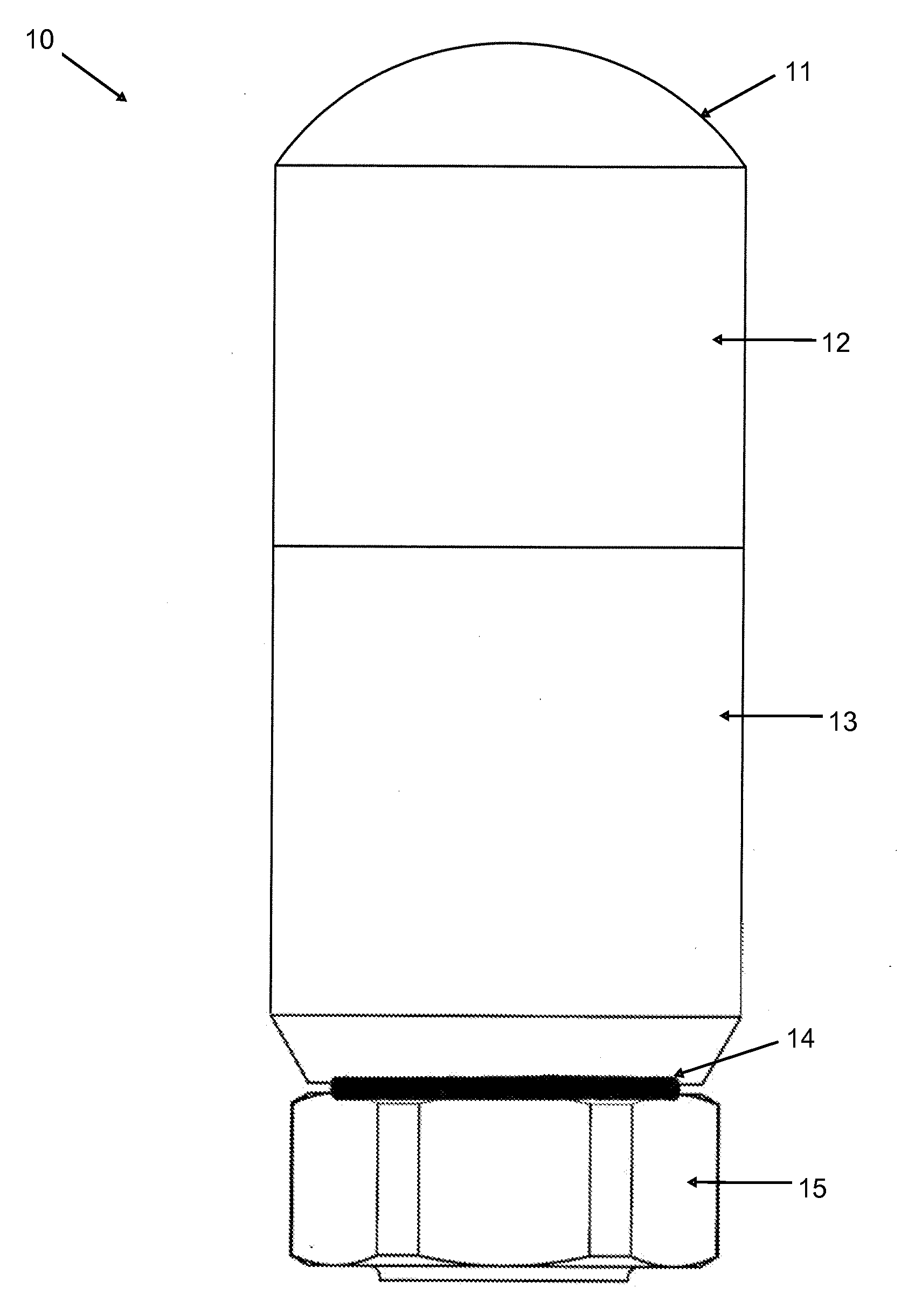
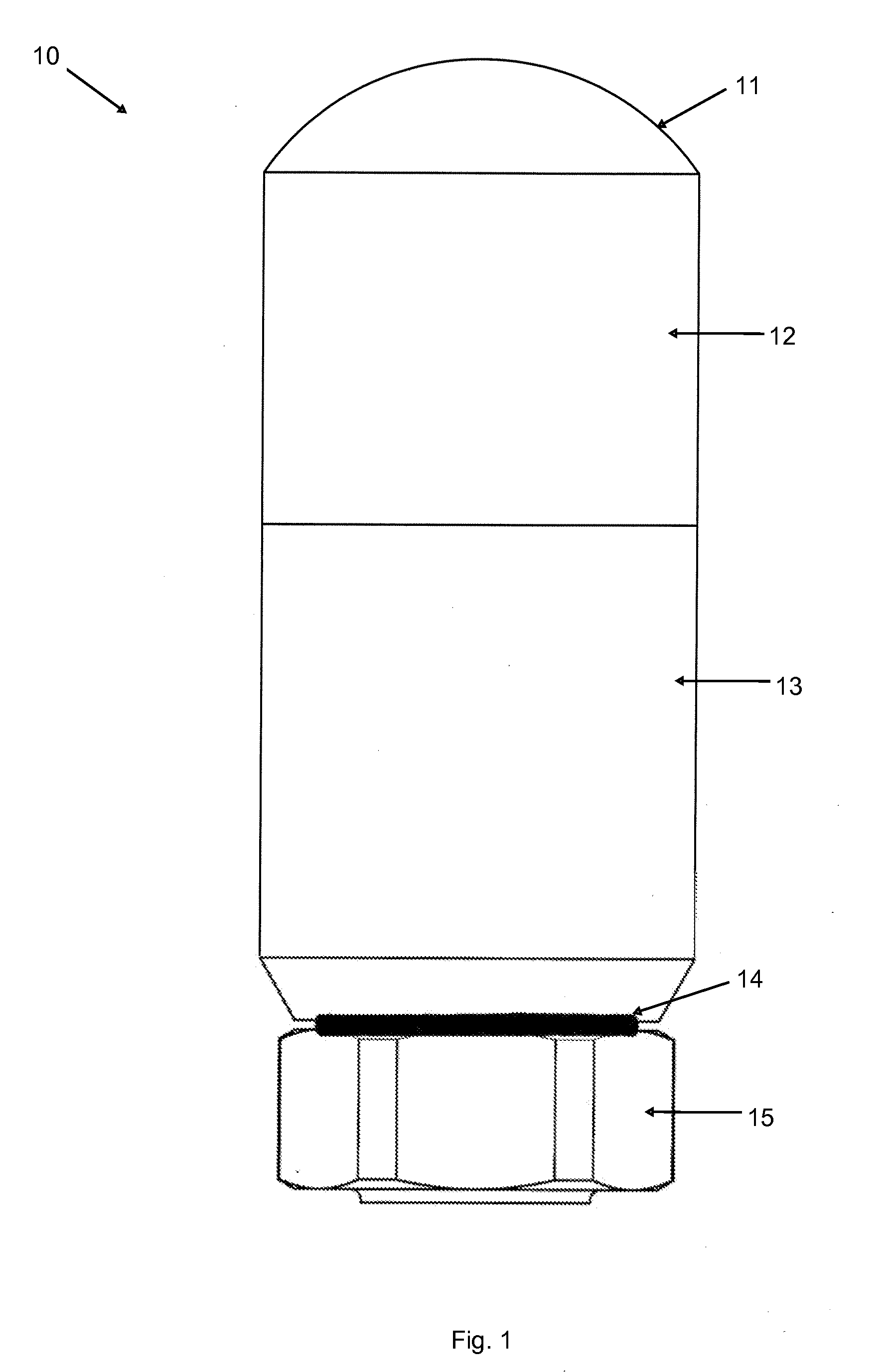
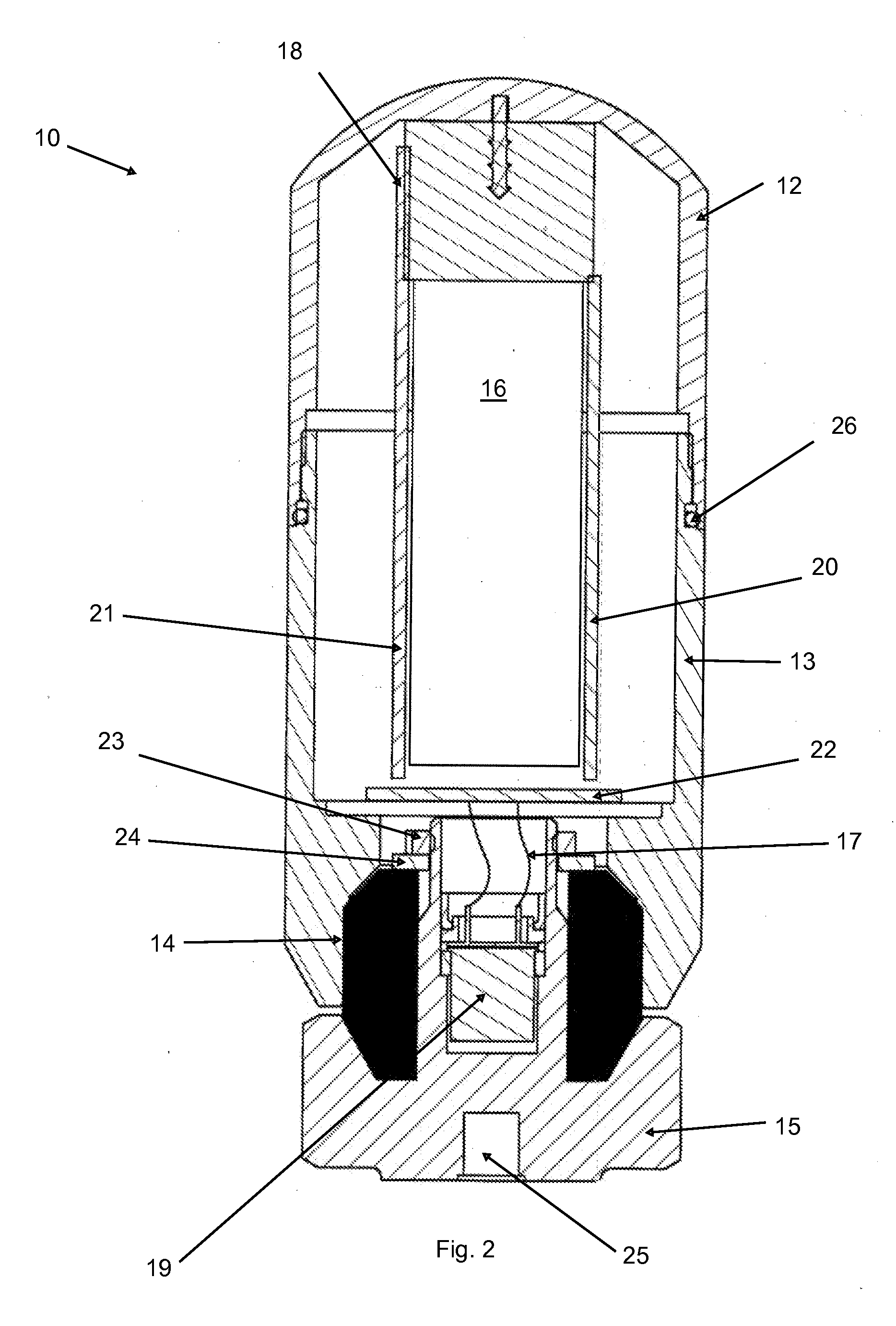
An apparatus and system for sensing vibration in rotary or reciprocating machinery, such as motors, pumps, fans, gearboxes, compressors, turbo-machinery or high-speed spindles, which comprises a mechanical isolation member (14) interposed between a sensor base (15) and a main sensor body (11). In one aspect, the mechanical isolation member comprises a coaxial cylinder of plastic, rubber or polyurethane which is compressed between the sensor base and main sensor body.

Description

PRIORITY CLAIM[0001]The present application claims priority to U.S. Provisional Patent Application No. 61 / 248,846, filed Oct. 5, 2009.TECHNICAL FIELD[0002]The present invention relates generally to a vibration sensor for use with machines such as rotary and reciprocating machinery, for example.BRIEF SUMMARY OF THE INVENTION[0003]With parenthetical reference to the corresponding parts, portions or surfaces of the disclosed embodiment, merely for purposes of illustration and not by way of limitation, the present invention provides an apparatus and system for sensing vibration which comprises a mechanical isolation member (14) interposed between a sensor base (15) and a main sensor body (11). In one aspect of the invention, the apparatus and system is mounted on or attached to a rotary or reciprocating machine such as a motor or pump. In one aspect, the apparatus and system is configured to sense and measure vibration in rotary and reciprocating machinery. In another aspect, the appara...

Claims


Application Information

Patent Timeline
Patent Type & Authority Applications(United States)
IPC IPC(8): G01M13/00
CPCG01M13/045
Inventor ZUSMAN, GEORGECORELLI, DAVID A.
Owner PCB PIEZOTRONICS
Learn More