Movable pipeline tee

a technology of moving pipelines and tees, which is applied in the direction of pipe supports, pipe laying and repair, mechanical equipment, etc., can solve the problems of increasing the cost of sandbag placement in subsea situations, rapid galvanic corrosion on one or other pipelines, and increasing the cost of sandbag placement. to prevent coating damage and resultant corrosion

Active Publication Date: 2011-04-07
VANDER LINDEN III PAUL G +1
View PDF13 Cites 12 Cited by
  • Summary
  • Abstract
  • Description
  • Claims
  • Application Information

AI Technical Summary

Benefits of technology

[0009]The object of this invention is to provide a method for separating the upper and lower pipelines to prevent coating damage and resultant corrosion.

Problems solved by technology

The first problem of crossing pipelines is simply than one pipelines on the other can damage the coating on the pipelines and the difference in electrical potential can cause rapid galvanic corrosion on one or other of the pipelines.
The process of placing sandbags in subsea situations is expensive, and gets more expensive as depths increase.
In the short time this scrapes the coatings off and promotes galvanic corrosion.

Method used


Image

  • Movable pipeline tee
  • Movable pipeline tee
  • Movable pipeline tee

Examples


Embodiment Construction

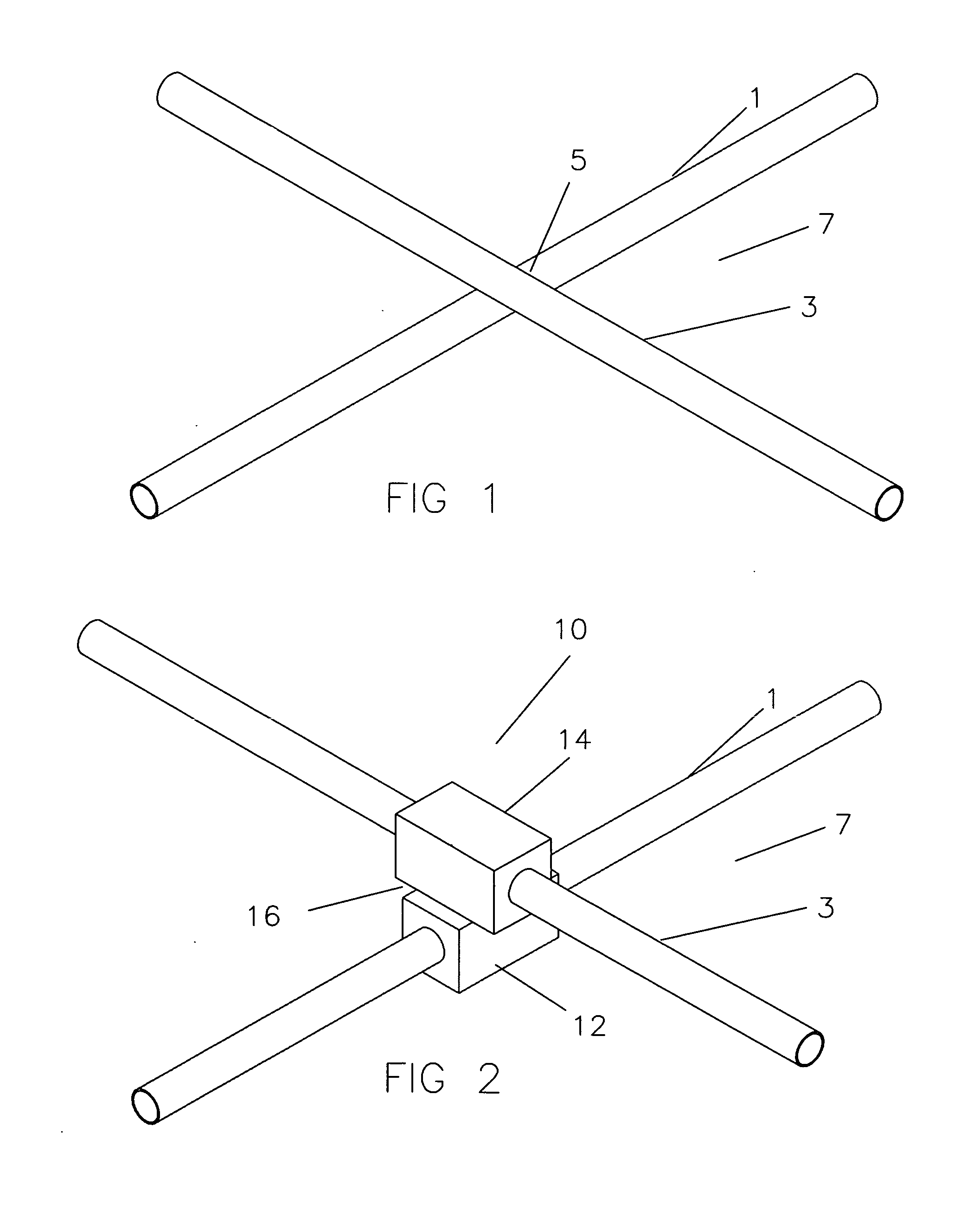
[0018]Referring now to FIG. 1, a lower pipeline 1 is shown being crossed by an upper pipeline 3 at crossing point 5 on the seafloor 7.

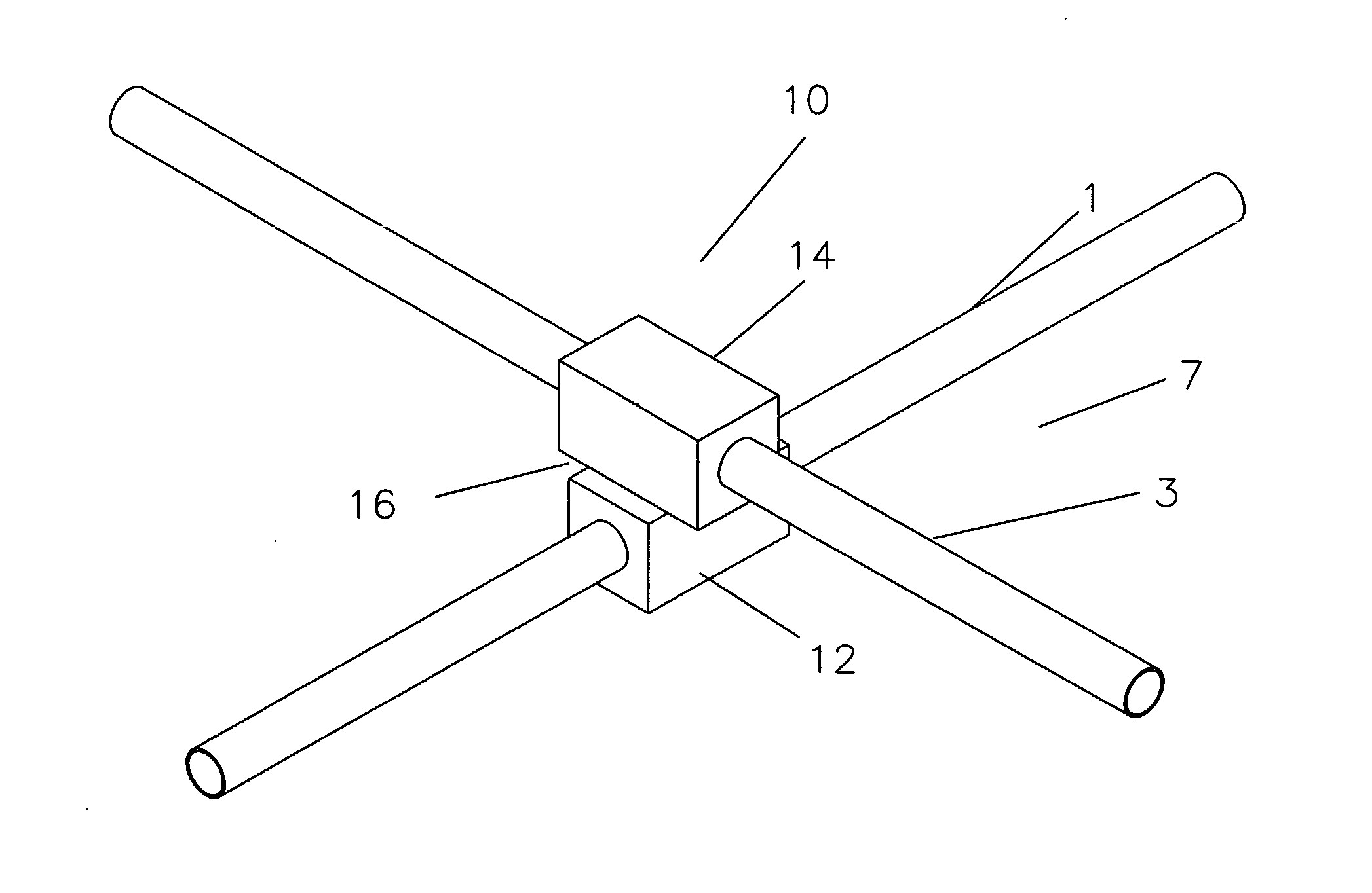
[0019]Referring now to FIG. 2 shows pipeline tee 10 with upper clamp section 12 around upper pipeline 3 and lower clamp section 14 around lower pipeline 1. Upper clamp section 12 and lower pipeline clamp 14 are rotatably connected at 16 to allow the two sections to adjust to the angular orientation of the pipelines.

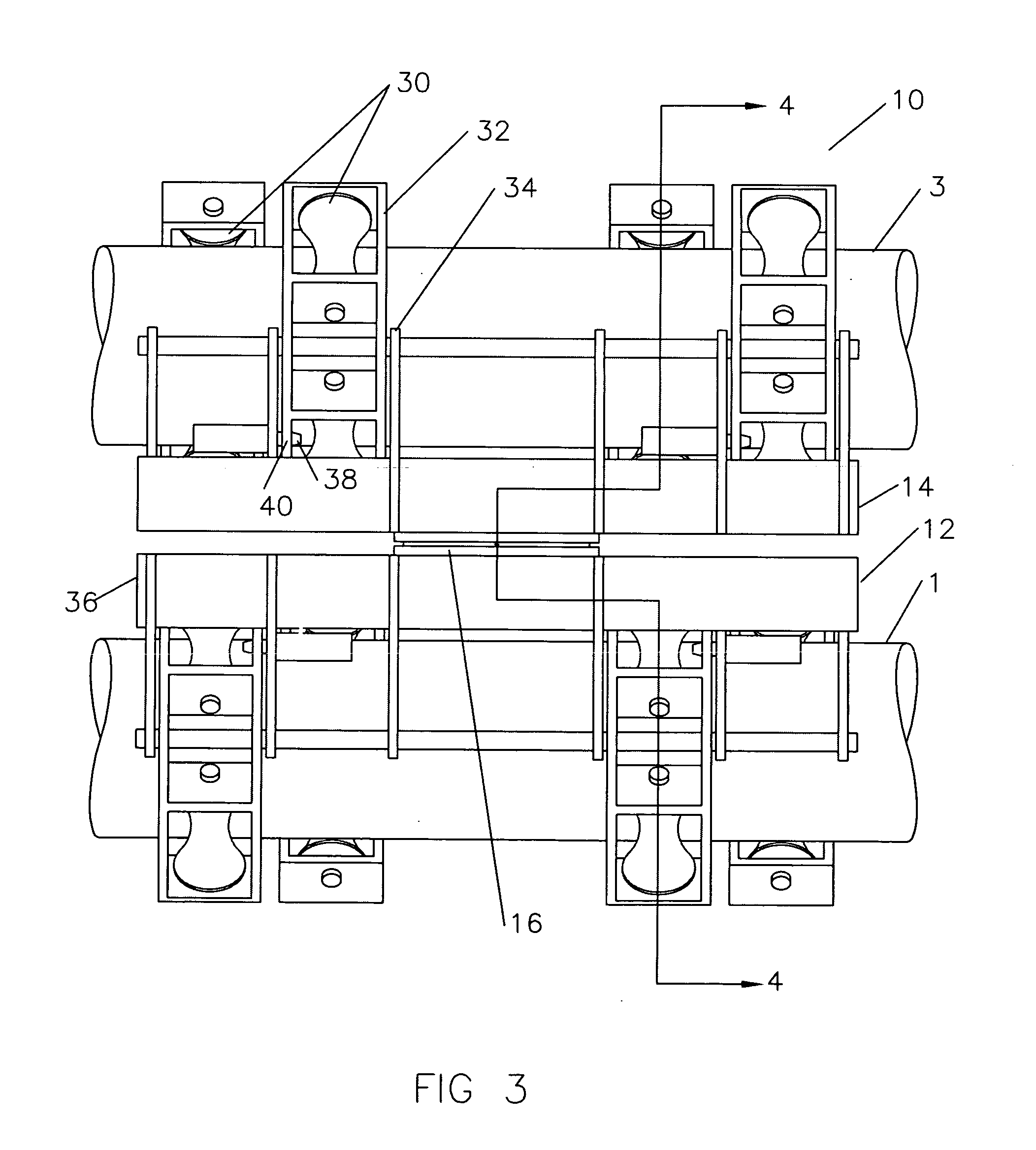
[0020]Referring now to FIG. 3 a side view of pipeline tee is shown is the position as would be clamped around the two pipeline if the pipelines were parallel rather than crossing. A multiplicity of rollers 30 are mounted on rockers 32 which are in turn mounted on frames 34 and 36. Spring loaded pins 38 lock into holes 40 when rockers 32 rock to the proper orientation to lock around the pipelines.

[0021]Referring now to FIG. 4 the pipeline tee 10 is in the open position and is approaching the upper pipeline 3. It is being lowered by a line (n...


PUM


Abstract

The method of protecting two subsea pipelines which cross each other in a subsea environment from damaging one another when subsea currents slide the upper pipeline along the upper surface of the lower pipeline by providing roller around the upper pipeline and rollers around the lower pipeline which are connected together by a rotatable connection which allows the sets of roller to match the angle of the pipeline.

Description

TECHNICAL FIELD[0001]This invention relates to the general subject of protecting subsea pipelines which cross and may damage one another.CROSS-REFERENCE TO RELATED APPLICATIONS[0002]Not applicable.STATEMENT REGARDING FEDERALLY SPONSORED RESEARCH OR DEVELOPMENT[0003]Not applicableREFERENCE TO A “MICROFICHE APPENDIX”[0004]Not applicableBACKGROUND OF THE INVENTION[0005]The field of this invention is that of the crossing of subsea pipelines and the damage which can happen to them when crossed. The pipeline infrastructure in the Gulf of Mexico (and other places in the world) on a map looks a lot like the road system on land. There are many pipelines, many pipeline intersections, and many pipelines which cross over one another.[0006]The first problem of crossing pipelines is simply than one pipelines on the other can damage the coating on the pipelines and the difference in electrical potential can cause rapid galvanic corrosion on one or other of the pipelines. This problem is convention...

Claims


Application Information

Patent Timeline
Patent Type & Authority Applications(United States)
IPC IPC(8): F16L1/00
CPCF16L1/20F16L3/237F16L3/18
Inventor VANDER LINDEN, III, PAUL G.BAUGH, BENTON F.
Owner VANDER LINDEN III PAUL G
Why Eureka
Try Eureka