Externally reinforced percutaneous gastrostomy tube with customizable smooth tube length
a gastrostomy tube and external reinforcement technology, applied in the field of external reinforcement percutaneous gastrostomy tubes with customizable smooth tube lengths, can solve the problems of frequent recurrence of weight gain, inability to improve related co-morbidities, and major health problems of obesity, and achieve the effect of facilitating facilitating preferential tearing of elastomeric materials
- Summary
- Abstract
- Description
- Claims
- Application Information
AI Technical Summary
Benefits of technology
Problems solved by technology
Method used
Image
Examples
first embodiment
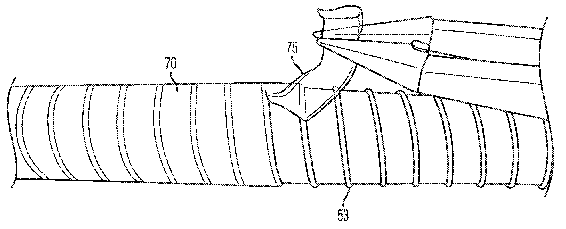
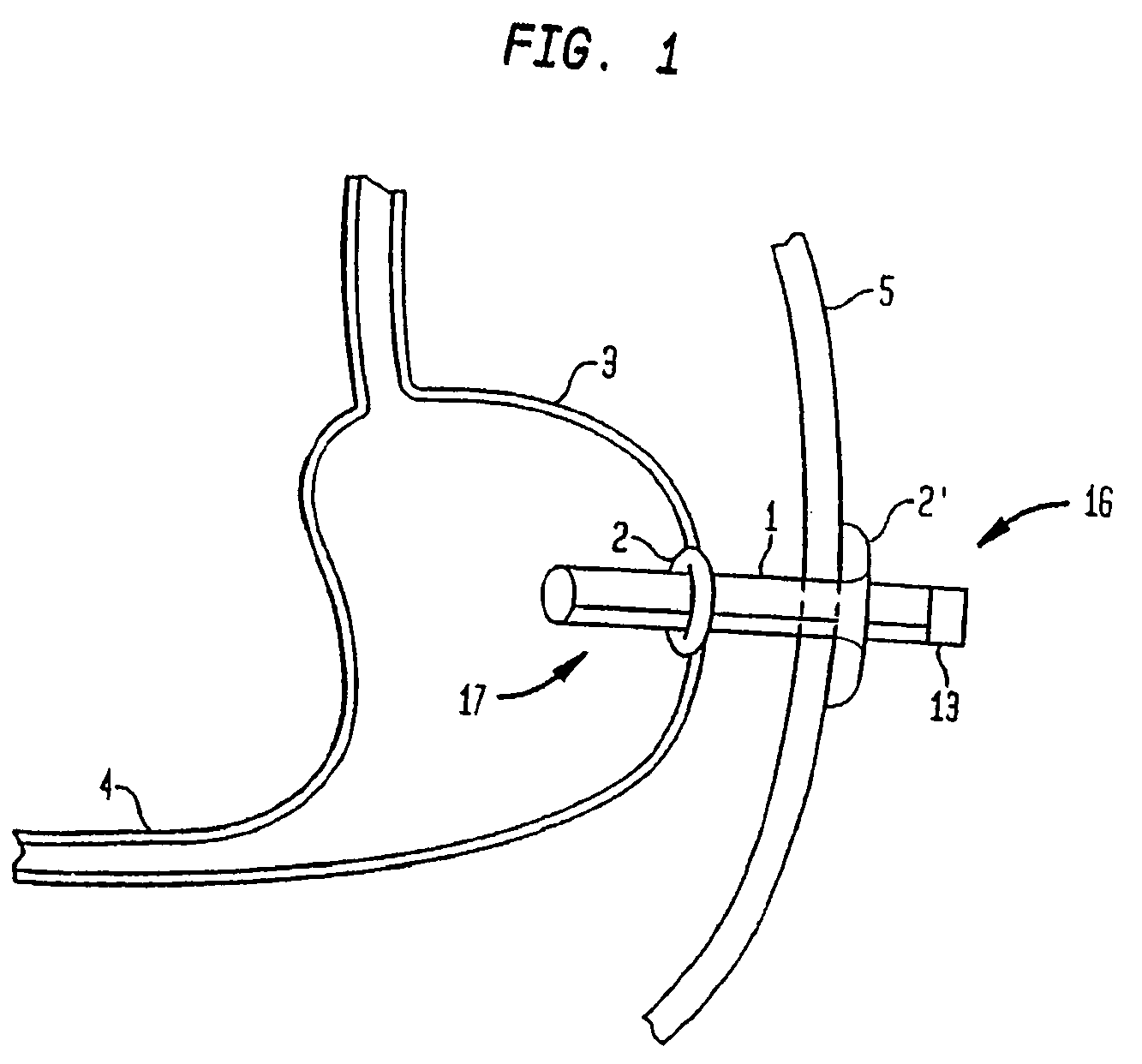
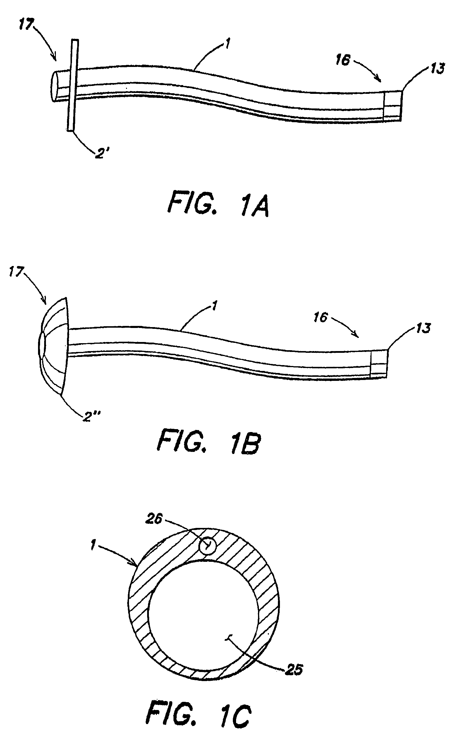
[0037]In the present invention as shown in FIG. 1, a transabdominal tube 1 is placed through a patient's abdominal wall such that a distal end portion 17 of the tube 1 is disposed inside the stomach 3 of the patient and a proximal end portion 16 of the tube 1 extends out from the skin 5 of the patient. The tube 1 preferably has a diameter that is 20 to 36 French in size (1 French=⅓ mm) Most preferably, the tube has a relatively large inner diameter (e.g., greater than 6.3 mm internal diameter) and the tube resists collapsing when extraction is performed. Optionally, the tube 1 may be stiffened, made durable and less collapsible by, for example, braiding the tube using nylon. Alternatively, the tube may be wrapped with wire material. Suitable materials for the tube 1 include polyurethane, silicone and other similar materials. The tube 1 may be opaque.
[0038]A retention member is attached to the tube 1 to prevent the tube 1 from falling out of the patient. In some embodiments, the rete...
second embodiment
[0062]FIG. 6 illustrates the present invention in which a feeling of satiety is created in the patient by inflating the balloon anchor. Creating a feeling of satiety curbs the patient's hunger and desire to eat food thereby allowing the patient to eat less and lose weight. As shown in FIG. 6, the inflation portion 2, which is the retention member that holds the tube 1 in the patient's stomach, also serves the function of decreasing stomach capacity to create a feeling of satiety when it is inflated. The inflation portion 2 may be variably inflated by adding or removing fluid through the inflation lumen 26 of the tube 1 (shown in FIG. 1C).
[0063]FIG. 7 shows an axial cross sectional view of the tube 1 extending out from the skin 5 of the patient in which the removal lumen 25 and the inflation lumen 26 are visible. In a feature which may be incorporated into any of the various embodiments of the present invention, a valve 15 is provided at the proximal end portion 16 of the tube 1 in t...
third embodiment
[0065]FIG. 8 illustrates the present invention showing a tube having two balloons attached to that portion of the tube that is disposed within the patient's upper digestive system. The balloon anchor 2 is expandable to about 10 ml and is positioned up against the stomach wall to prevent the tube 1 from falling out. The inflatable balloon 29 is expandable from about 100 ml to about 850 ml and may be expanded intermittently to limit the capacity of the stomach. For example, the balloon 29 may be inflated via an inflation lumen prior to a meal to create the sensation of being full. After the meal, the balloon 29 may be deflated to prevent chronic accommodation. An electrically or a manually operated pump may be used to cause the inflation.
[0066]The tube 1 in this embodiment has a long inner tube length of about 10 cm or longer and a diameter of 28 French (9.3 mm) in size or greater. The tube 1 may have multiple holes 32 in the sidewall of its distal end portion 17 as shown in FIG. 8 an...
PUM
 Abstract
Description
Claims
Application Information
 - R&D
- Intellectual Property
- Life Sciences
- Materials
- Tech Scout
- Unparalleled Data Quality
- Higher Quality Content
- 60% Fewer Hallucinations
Browse by: Latest US Patents, China's latest patents, Technical Efficacy Thesaurus, Application Domain, Technology Topic, Popular Technical Reports.
© 2025 PatSnap. All rights reserved.Legal|Privacy policy|Modern Slavery Act Transparency Statement|Sitemap|About US| Contact US: help@patsnap.com


