Device and method for activating a communication unit

Inactive Publication Date: 2011-04-14
AALBORG UNIV
View PDF13 Cites 15 Cited by
  • Summary
  • Abstract
  • Description
  • Claims
  • Application Information

AI Technical Summary

Benefits of technology

[0009]With such communication system, a device in the system is capable of saving energy in idle mode where the communication unit, e.g. a GSM unit, is not used, since a short range receiver unit with low power consumption, e.g. a completely different wireless technology than used by the first communication channel, can be used to monitor for incoming messages during idle mode. This is advantageous especially within mobile or portable battery powered devices. In case the receiver unit is a passive unit, e.g. an RFID tag, the idle power consumption can be reduced to zero, in case the communication unit is completely shut off in the in-active power saving mode. The communication unit is only switched to its active (power consuming) mode by the receiver unit, when a wake-up signal is received, e.g. indicating an incoming call to the communication unit.
[0010]The system is especially suited for use in groups of devices closely spaced, e.g. within an office etc., where one coordinator device maintains its communication unit active so as to be able to receive calls on the first wireless communication channel to a device in th

Problems solved by technology

However, even with such timer function, the communication unit will in many applications stay in idle mode most of the time it is switched on, and thus drain the batter

Method used


Image

  • Device and method for activating a communication unit
  • Device and method for activating a communication unit

Examples


Example

[0042]The figures illustrate specific ways of implementing the present invention and are not to be construed as being limiting to other possible embodiments falling within the scope of the attached claim set.

DETAILED DESCRIPTION OF EMBODIMENTS

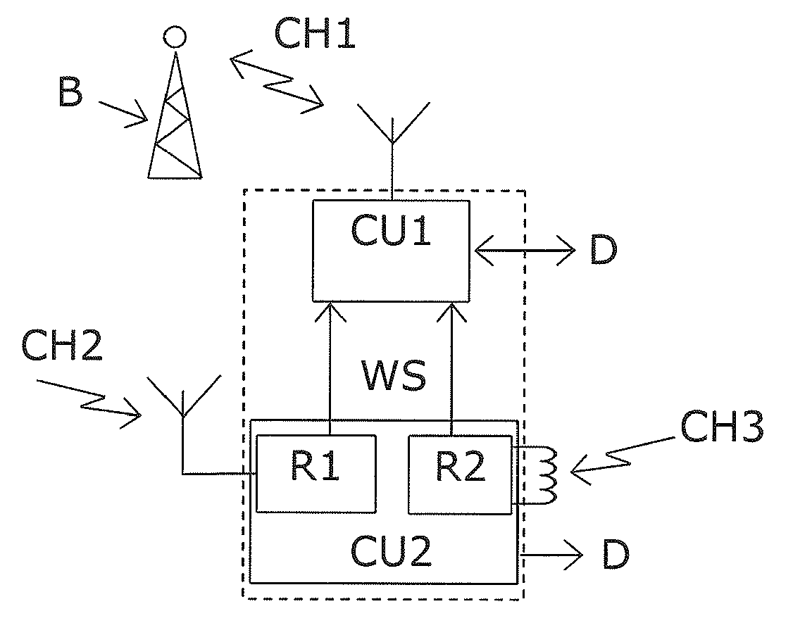
[0043]FIG. 1 shows an embodiment of a device according to the first aspect of the invention. The device includes a first communication unit CU1 arranged to two-way communicate with an external base station B, e.g. at a distance of several 100 meters, on a first wireless communication channel CH1, e.g. GSM. The first communication unit CU1 can two-way communicate data D with the base station B. The device also includes a second communication unit CU2 including a first receiver unit R1 arranged to receive a wake-up signal on a second wireless communication channel CH2, e.g. a short range RF channel such as Bluetooth. Further, the second communication unit CU2 includes a second receiver unit R2 arranged to receive a wake-up signal on a third wirel...


PUM


Abstract

A communication system with a plurality of devices with a communication unit (CU1) arranged to communicate on a first wireless communication channel (CH1), e.g. GSM, in an active mode. Otherwise, the communication unit (CU1) is in an in-active power saving mode. A receiver unit (R1, R2) receives a wake-up signal on a second wireless communication channel (CH2, CH3), e.g. RFID. The receiver unit (R1, R2) then switches the communication unit (CU1) into active mode. The second wireless communication channel (CH2, CH3) is dedicated for wake-up signals and is in a different frequency band than the first wireless communication channel (CH1). Further, the first wireless communication channel (CH1) has a larger distance range than the second wireless communication channel (CH2, CH3). A coordinator device (CD) receives a call on the first wireless communication channel (GSM) and transmits a wake-up signal on the second wireless communication channel (RFID) in order to activate communication units (D1, D2, D3, D4) in a group of the plurality of devices (D1, D2, D3, D4). Hereby power can be saved to the typically more power demanding communication unit (CU1) arranged for long distance communication, while only limited or even zero power is used to monitor for wake-up signals on a short range channel (CH2, CH3). The system is suitable for groups of a plurality of rather closely spaced devices (D1, D2, D3, D4), where one active coordinator device (CD) is used to receive incoming calls on behalf of a group of devices (D1, D2, D3, D4) having their communication units in power saving mode until the coordinator device (CD) activates them.

Description

FIELD OF THE INVENTION[0001]The present invention relates to the field of communication technology, especially wireless communication technology. More specifically, the invention provides a device and a method for activating a communication unit in a communication device so as to save power when the communication unit is in idle mode.BACKGROUND OF THE INVENTION[0002]Energy saving is important in battery driven mobile communication devices. Mobile communication devices typically have communication units, e.g. Radio Frequency (RF) receivers and transmitters, which can be automatically switched on and off based on a timer, so as to save power to the communication unit when not used. However, even with such timer function, the communication unit will in many applications stay in idle mode most of the time it is switched on, and thus drain the battery of the mobile device at no use. E.g. a mobile phone is often switched on for a long time without receiving any call.[0003]US 2003 / 0112126 ...

Claims


Application Information

Patent Timeline
IPC IPC(8): H04Q5/22
CPCY02B60/50H04W52/0229Y02D30/70
Inventor FITZEK, FRANK HANNS PAUL
Owner AALBORG UNIV
Why Eureka
Try Eureka