Adjustable Door Stop System
- Summary
- Abstract
- Description
- Claims
- Application Information
AI Technical Summary
Benefits of technology
Problems solved by technology
Method used
Image


Examples
embodiment 10
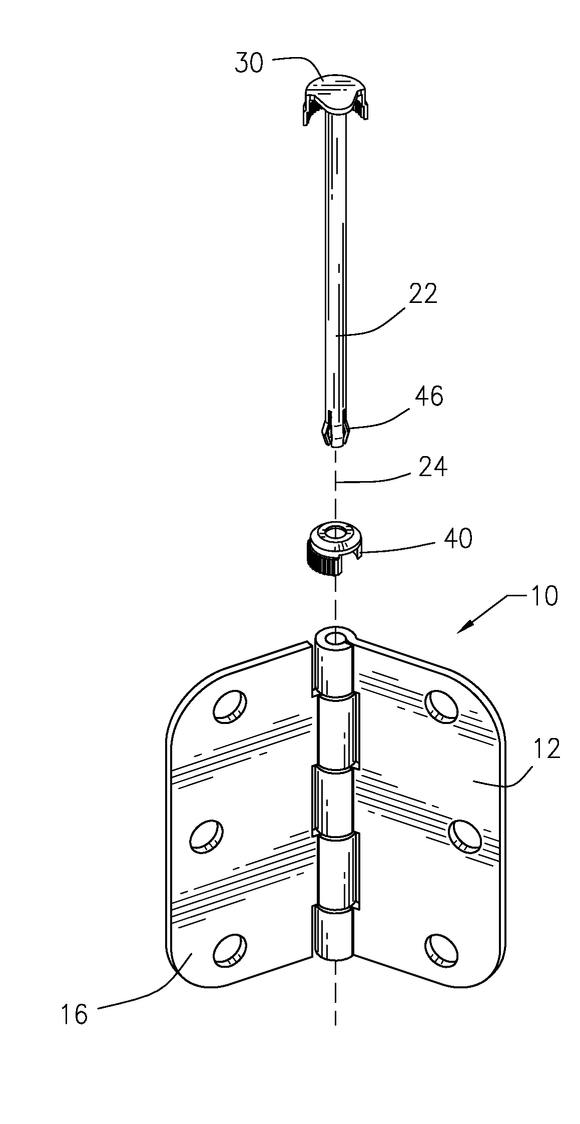
[0040]FIG. 1 illustrates a perspective view of a first preferred embodiment 10 of an adjustable door stop system constructed in accordance with present invention for a hinge mounted door and FIG. 2 illustrates an exploded view of an adjustable door stop system 10 shown in FIG. 1 apart from the door and doorway.
[0041]One hinge leaf 12 would be connected to a door 14 in a known manner, such as with fasteners. Another hinge leaf 16 would be connected to a doorway 18 in a known manner, such as with fasteners. The present invention may be employed with a wide variety of doors and doorways.
[0042]The adjustable door stop system includes a hinge pin 22 with a cylindrical barrel having an axis (illustrated by dashed lines 24 in FIG. 2) so that the hinge leaves rotate around the axis 24.
[0043]FIG. 3 illustrates a perspective view of the assembled adjustable door stop system 10 apart from the door and the doorway. FIG. 4 illustrates a top view of the adjustable door stop system 10 shown in FIG...
embodiment 50
[0059]FIGS. 8 and 9 illustrate perspective views of a second preferred embodiment 50 of an adjustable door stop system for a hinge mounted door. FIG. 8 illustrates the door stop system 50 with the door 54 in a closed position while FIG. 9 illustrates the door in an open position.
[0060]One hinge leaf 52 would be connected to the door 54 while another hinge leaf 56 would be connected to a doorway 58.
[0061]FIG. 10 illustrates an exploded view of the adjustable door stop system 50 apart from the door and the doorway. The door stop system 50 includes a hinge pin 60 with a cylindrical barrel having an axis 62 (shown by dashed lines) so that the hinge leaves 56 and 58 rotate about the axis.
[0062]FIG. 11 illustrates a perspective view of the adjustable door stop system 50 shown in FIG. 10 fully assembled. FIG. 12 illustrates a portion of the hinge pin 60 with a movement control cap (to be described) partially raised.
[0063]As best seen in FIGS. 10 and 12, a first finger 70 extends radially a...
PUM
 Abstract
Description
Claims
Application Information