Device and method for humidity estimation

a technology of humidity estimation and humidity measurement, applied in the direction of instruments, heating types, static/dynamic balance measurement, etc., can solve the problems of not having a humidity measurement instrument in many buildings, and difficult to control the humidity environmen

Inactive Publication Date: 2011-04-21
KK TOSHIBA
View PDF17 Cites 15 Cited by
  • Summary
  • Abstract
  • Description
  • Claims
  • Application Information

AI Technical Summary

Benefits of technology

[0028]An object of embodiments is to provide a device and a method for humidity estimation that can estimate an indoor humidity value to be used for air-conditioning even in a building where no humidity measurement instrument is equipped.

Problems solved by technology

But no humidity measurement instrument is equipped in many buildings.
Therefore, it is hard to perform a control of humidity environment.

Method used


Image

  • Device and method for humidity estimation
  • Device and method for humidity estimation
  • Device and method for humidity estimation

Examples


Embodiment Construction

easurement instrument is equipped.

BRIEF DESCRIPTION OF DRAWINGS

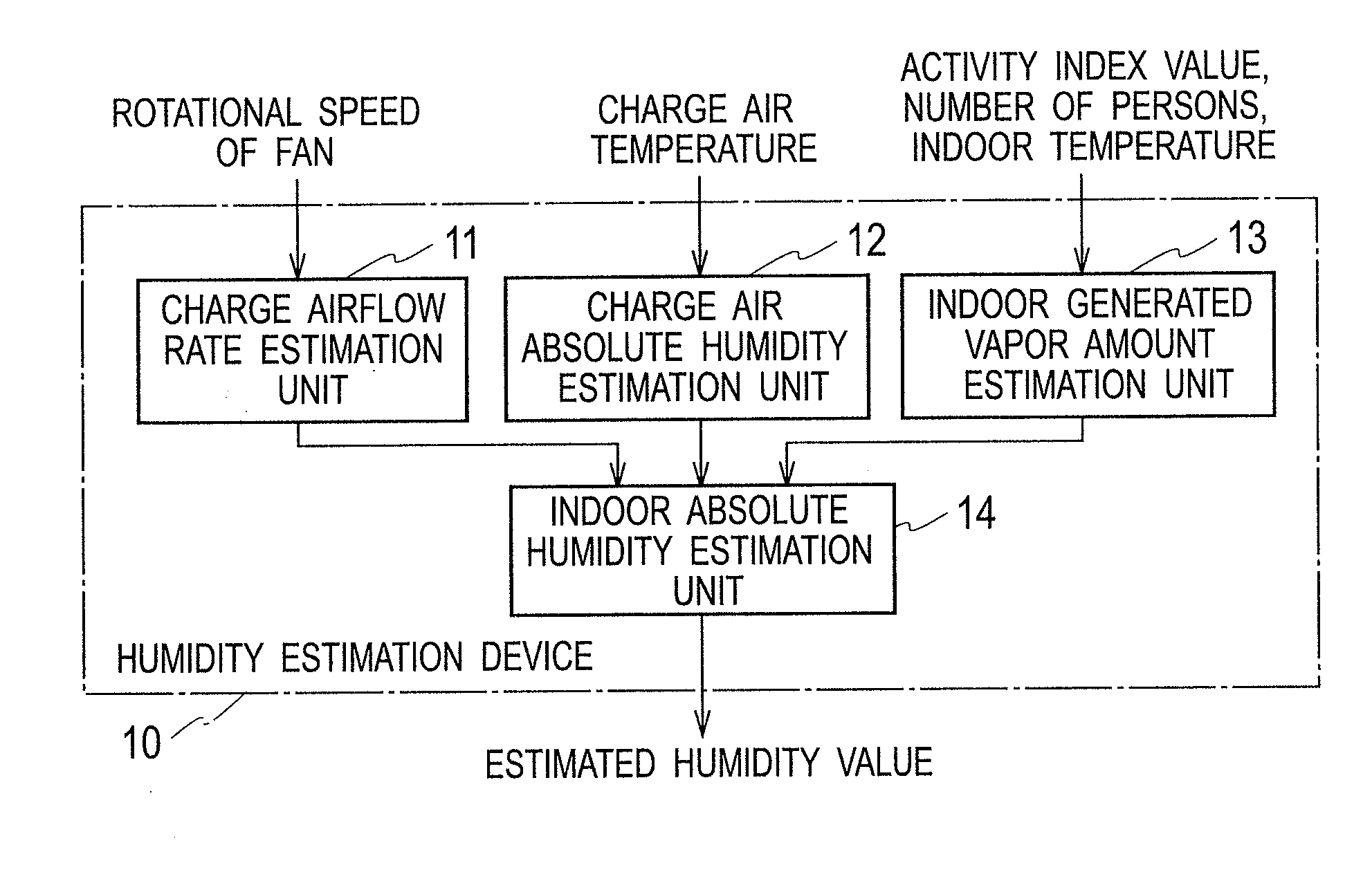
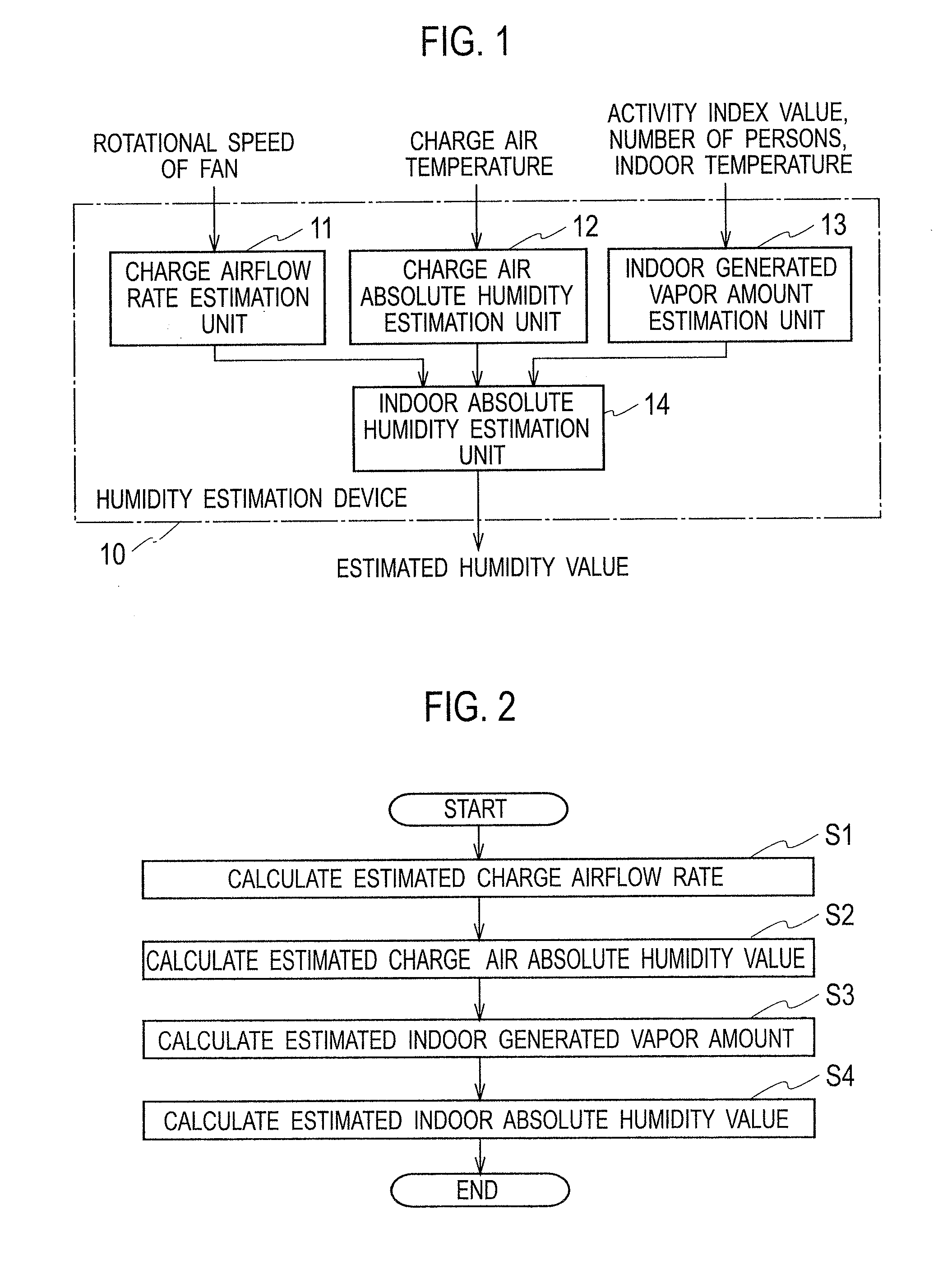
[0032]FIG. 1 is a block diagram of a device for humidity estimation according to an embodiment;

[0033]FIG. 2 is a flowchart showing operations of the device for humidity estimation;

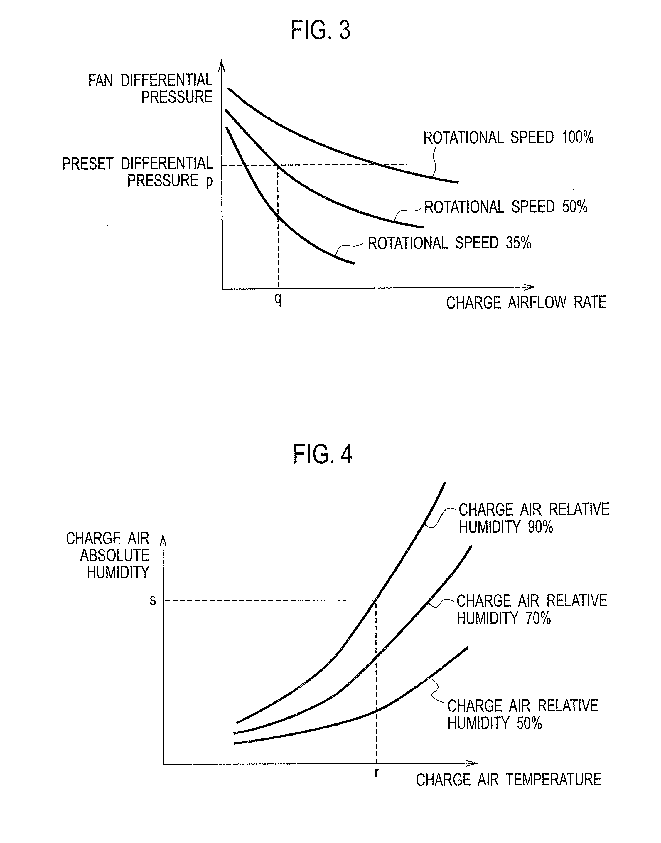
[0034]FIG. 3 is a graph showing information of a charge airflow rate table stored in a charge airflow rate estimation unit of the device for humidity estimation;

[0035]FIG. 4 is a graph showing information of a charge air humidify table stored in a charge air absolute humidity estimation unit of the device for humidity estimation; and

[0036]FIG. 5 is a graph showing information of a generated vapor amount table stored in an indoor generated vapor amount estimation unit of the device for humidity estimation.

DETAILED DESCRIPTION OF EMBODIMENTS

Configuration of Device for Humidity Estimation

[0037]Hereinafter, configuration of an embodiment of a humidity estimation device 10 will be explained with reference to FIG. 1.

[0038]The humidity estimation devi...


PUM

PropertyMeasurementUnit
temperatureaaaaaaaaaa
absolute humidityaaaaaaaaaa

Abstract

A humidity estimation device connected with an air-conditioner includes a charge airflow rate estimation (CARE) unit, a charge air absolute humidity estimation (CAAHE) unit, an indoor generated vapor amount estimation (IGVAE) unit, and an indoor absolute humidity estimation (IAHE) unit. The CARE unit calculates an estimated charge airflow rate (ECAR) of the air-conditioner based on operation control information of the charge fan and a preset fan differential pressure. The CAAHE unit calculates an estimated charge air absolute humidity (ECAAH) of the air-conditioner based on a charge air temperature and a preset charge air relative humidity. The IGVAE unit calculates an estimated indoor generated vapor amount (EIGVA) based on an indoor temperature, the number of persons in the room and activity index values of the persons. The IAHE unit calculates an estimated absolute humidity in the room based on the ECAR, the ECAAH and the EIGVA.

Description

CROSS-REFERENCE TO RELATED APPLICATION[0001]This application is based upon and claims the benefit of priority from Japanese Patent Application No. 2009-238557, filed Oct. 15, 2009; the entire contents of which are incorporated herein by reference.FIELD[0002]Embodiments described herein relate generally to a device and a method for humidity estimation that estimate an indoor humidity value to be used for calculating air-conditioning parameters in an air-conditioner that controls air-conditioning within a building such as a hospital.BACKGROUND[0003]Generally, energy consumption relating to air-conditioning occupies a half of energy consumption for all building equipments. Therefore, promotion of energy saving for air-conditioning highly contributes to energy saving for entire of building equipments.[0004]Meanwhile, it is required to satisfy sensation of warmth (i.e. comfort) of persons in an amenity space such as a room in a business building. Though ensuring comfort has aspects oppos...

Claims


Application Information

Patent Timeline
Patent Type & Authority Applications(United States)
IPC IPC(8): G01N19/10
CPCF24F11/0015F24F11/30F24F2110/20F24F11/62F24F2110/10F24F2120/12F24F2120/14
Inventor TAKAGI, YASUOIKEDA, KOICHIHIRAOKA, YUKIOKOBAYASHIFUJII, AKIHIRO
Owner KK TOSHIBA
Why Eureka
Try Eureka