Imaging apparatus for generating an image of a region of interest

a technology of imaging apparatus and region, applied in the direction of optical radiation measurement, instruments, applications, etc., can solve the problems of different modification of projection data, and achieve the effect of accurate identification, reduced unnecessary radiation dose, and small density weigh

Inactive Publication Date: 2011-04-28
KONINKLIJKE PHILIPS ELECTRONICS NV
View PDF11 Cites 12 Cited by
  • Summary
  • Abstract
  • Description
  • Claims
  • Application Information

AI Technical Summary

Benefits of technology

[0012]The invention is based on the idea that high density detection data, i.e. detection data which could be corrupted because the corresponding radiation has passed the high density region, are less density weighted than the non-high density detection data. Thus, high density artifacts in reconstructed images are reduced by reducing the influence of detection data, which are likely to be corrupted, i.e. high density detection data, thereby reducing high density artifacts, in particular, metal artifacts, in the reconstructed image. The high density region is preferentially a metallic region within the region of interest. If a patient having metallic implants is located within the region of interest, the identification unit is preferentially adapted to identify the location, the shape and the dimensions of the metallic implant within the region of interest. The predefined density is preferentially chosen such that the identification unit identifies high density detection data, which depend on radiation, which has traversed a metallic region, and non-high density detection data, which depend on radiation, which has not traversed the metallic region.
[0014]In a preferred embodiment, the density weighting unit is adapted such that all high density detection data have a smaller density weight than the non-high density detection data. In a further preferred embodiment, at least a part or all of the high density detection data are density weighted with a zero value, wherein at least a part or all of the non-high density detection data are density weighted with a non-zero value. If all high density detection data are density weighted with a zero value, high detection data, which might be corrupted, are not used by the reconstruction unit for reconstructing an image of the region of interest, thereby further reducing high density artifacts in the reconstructed image.
[0018]It is further preferred that the imaging apparatus further comprises an aperture weighting unit for aperture weighting the detection data. This aperture weighting is preferentially performed such that detection data, which correspond to rays which are centrally located within the cone, obtain a higher aperture weight than more peripheral rays. In particular, detection data, which correspond to rays, which are more peripheral with respect to an intersection of the cone-beam and a plane, which traverses the radiation source position and in which the rotational axis is completely located, if the radiation source and the region of interest are rotated relative to each other by the moving unit, obtain a lower aperture weight than detection data, which correspond to rays, which are located more centrally within this intersection. A more detailed description of this aperture weighting is disclosed in the article “Aperture weighted cardiac reconstruction for cone-beam CT” by P. Koken and M. Grass, 3433-3448, Phys. Med. Biol. 51 (2006), which is herewith incorporated by reference. The aperture weighting further reduces artifacts, which can be generated, if different cone angles of different rays are not considered, and, thus, improves the quality of the reconstructed image.
[0019]It is further preferred that the reconstruction unit is adapted to perform a cone-beam reconstruction, in particular, and an aperture weighted cone-beam reconstruction, wherein the divergence of the rays in the cone angle direction is considered, wherein if, for example, the moving unit rotates the radiation source and the region of interest relative to each other around a rotational axis, the cone angle is defined as an angle between a first line, which is perpendicular to the rotational axis and which traverses the radiation source location, and a second line defining a ray, which is located within a plane parallel or identical to a plane defined by the first line and the rotational axis. This consideration of the cone angle improves the quality of the reconstructed image. For a detailed description of an aperture weighted cone-beam reconstruction reference is made to the above-mentioned article by Koken et al.
[0023]It is further preferred that the identification unit is adapted to forward project the determined high density region and to identify non-high density detection data as detection data outside the forward projected high density region and to identify high density detection data as detection data inside the forward projected high density region. This allows to accurately identify high density detection data and non-high density detection data.
[0024]It is further preferred that the moving unit is adapted to move the radiation source and the region of interest relative to each other along a helical trajectory, wherein the high density region is located off-center with respect to a central longitudinal axis of the helical trajectory, wherein the helical trajectory is adapted such that the high density region is longitudinally centered with respect to portions of windings of the helical trajectory having the shortest distance to the high density region. This reduces the fraction of high detection data of the detection data such that the fraction of detection data, which obtain a small density weight with respect to the density weight of non-high detection data or which are not used during the reconstruction, is reduced, thereby reducing unnecessary radiation dose applied on the region of interest, in particular, if a patient is located within the region of interest, on a patient.

Problems solved by technology

The use of such a computed tomography apparatus has the drawback that the modified projection data are still different to projection data, which would have been measured without the artifact creating object located within the patient, i.e. the modified projection data are still corrupted and produce therefore still artifacts in the final reconstructed image.

Method used


Image

  • Imaging apparatus for generating an image of a region of interest
  • Imaging apparatus for generating an image of a region of interest
  • Imaging apparatus for generating an image of a region of interest

Examples


Embodiment Construction

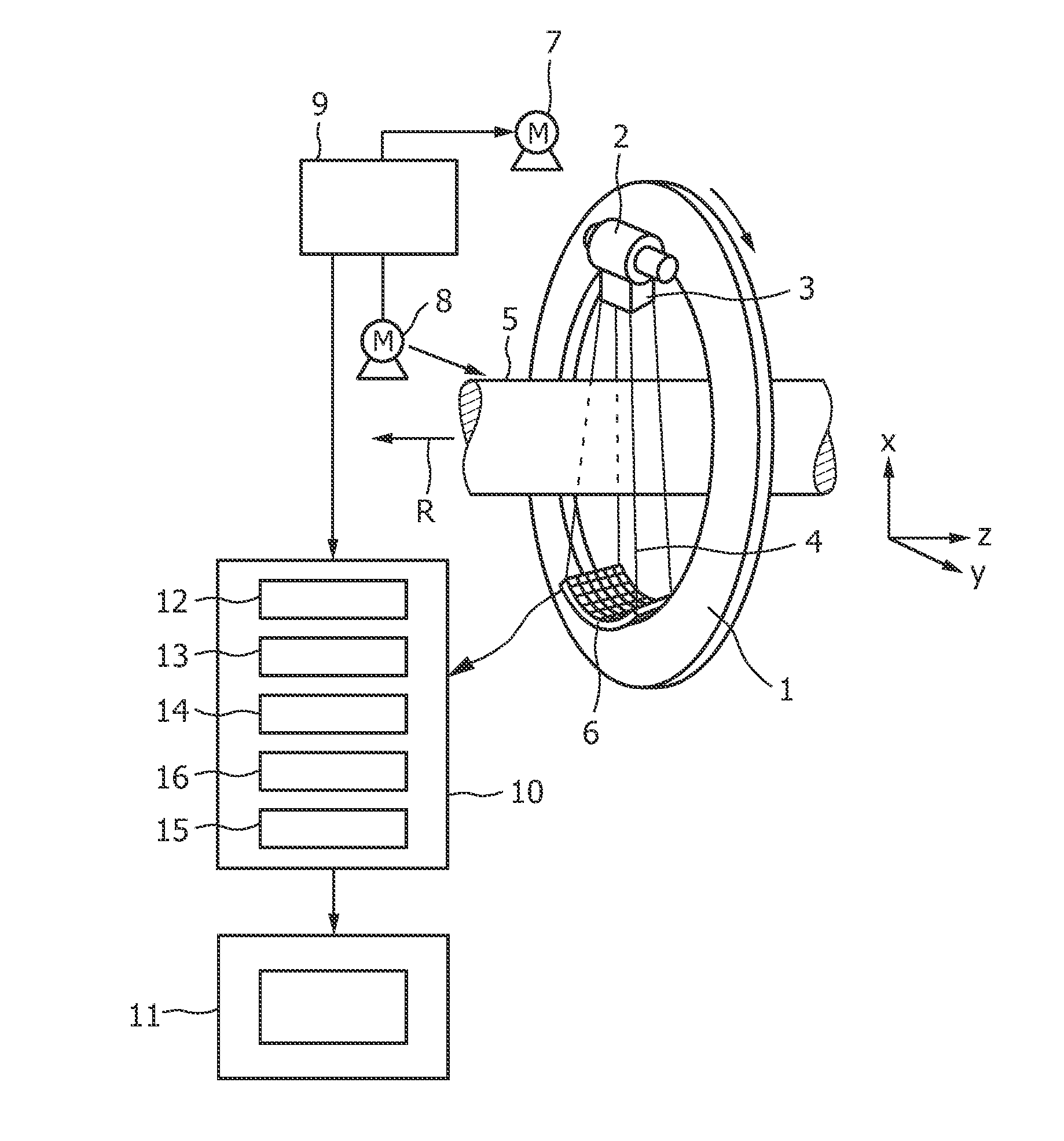
[0049]FIG. 1 shows schematically and exemplarily an imaging apparatus for generating an image of a region of interest being, in this embodiment, a computed tomography apparatus. The computed tomography apparatus includes a gantry 1, which is capable of rotation about a rotational axis R, which extends parallel to the z direction. A radiation source 2, which is, in this embodiment, an X-ray tube, is mounted on the gantry 1. The radiation source 2 is provided with a collimator 3, which forms, in this embodiment, a conical radiation beam 4 from the radiation generated by the radiation source 2. The radiation traverses an object (not shown), such as a patient, and a region of interest, which is preferentially located within the object, in an examination zone 5, which is, in this embodiment, cylindrical. After having traversed the examination zone 5 the radiation beam 4 is incident on the detection unit 6, which comprises, in this embodiment, a two-dimensional detection surface. The dete...


PUM


Abstract

The present invention relates to an imaging apparatus for generating an image of a region of interest. The imaging apparatus comprises a radiation source (2), a detection unit (6) for generating detection data and a moving unit (1, 7, 8) for moving the radiation source (2) and the region of interest relative to each other, while the detection data are generated. The imaging apparatus further comprises an identification unit (13) for identifying in the detection data high density detection data and non-high density detection data. A density weighting unit (14) density weights the detection data, wherein at least a part of the high density detection data has a smaller density weight than the non-high density detection data, and a reconstruction unit (15) reconstructs an image of the region of interest from the weighted detection data.

Description

FIELD OF THE INVENTION[0001]The present invention relates to an imaging apparatus, an imaging method and a computer program for generating an image of a region of interest. The invention relates further to an image generation device, an image generation method and an image generation computer program for generating an image of a region of interest.BACKGROUND OF THE INVENTION[0002]WO 2006 / 039809 A1 discloses a computed tomography apparatus being adapted for reducing metal artifacts in a reconstructed image. Projection data are acquired by a detection unit, while a radiation source and the detection unit move along a helical trajectory relative to a patient. A reconstruction unit reconstructs an image of the patient from the acquired projection data and an artifact creating object is determined in this reconstructed image, which can be regarded as a preliminary image. The determined artifact creating object is forward projected onto the detection unit and projection data located withi...

Claims


Application Information

Patent Timeline
Patent Type & Authority Applications(United States)
IPC IPC(8): A61B6/00G06K9/00
CPCA61B6/032A61B6/14A61B6/4085A61B6/027G06T11/005G06T2211/421A61B6/5252A61B6/5258
Inventor FORTHMANN, PETERKOEHLER, THOMASSCHMITT, HOLGER
Owner KONINKLIJKE PHILIPS ELECTRONICS NV
Why Eureka
Try Eureka