Connector assembly

a technology of connecting rods and connectors, applied in the direction of packaging foodstuffs, packaged goods types, pharmaceutical containers, etc., can solve the problems of inability to safely transfer liquid medical agents, easy pulling of hollow needles from rubber stoppers, etc., and achieve the effect of safe and assured transfer

Inactive Publication Date: 2011-05-05
TERUMO KK
View PDF12 Cites 95 Cited by
  • Summary
  • Abstract
  • Description
  • Claims
  • Application Information

AI Technical Summary

Benefits of technology

[0007]It is an object of the present invention to provide a connector assembly in which a liquid can be transferred safely and assuredly from the first connector side to the second connector side or in the reverse direction.

Problems solved by technology

However, the connector described in Patent Document 1 has a problem in that if a force such as to pull the hollow needle out of the rubber stopper of the vial container acts in the use condition, the hollow needle would be easily pulled out of the rubber stopper of the vial container.
In this case, the liquid medical agent may be scattered from the exposed needle point, and adhere to a medical care worker or the like, or the medical care worker may be punctured with the needle point by mistake.
Thus, there has been a problem that the liquid medical agent cannot be transferred safely and assuredly through the connector.

Method used


Image

  • Connector assembly
  • Connector assembly
  • Connector assembly

Examples


first embodiment

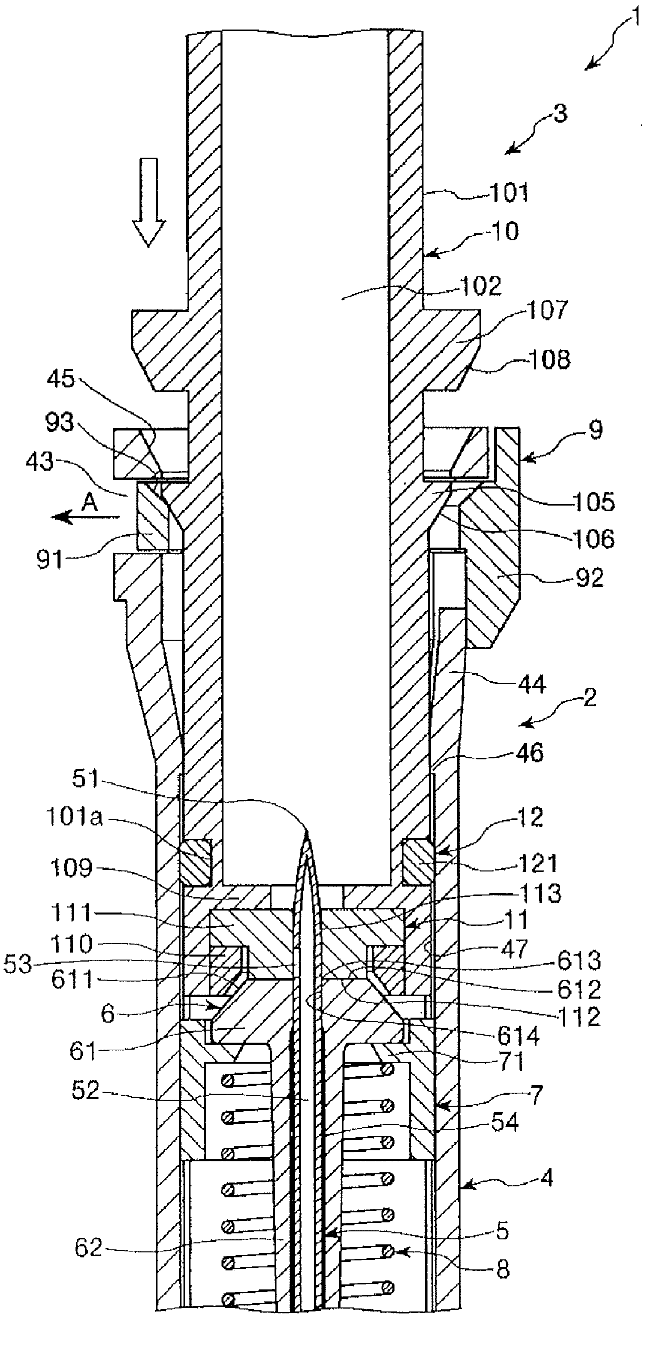
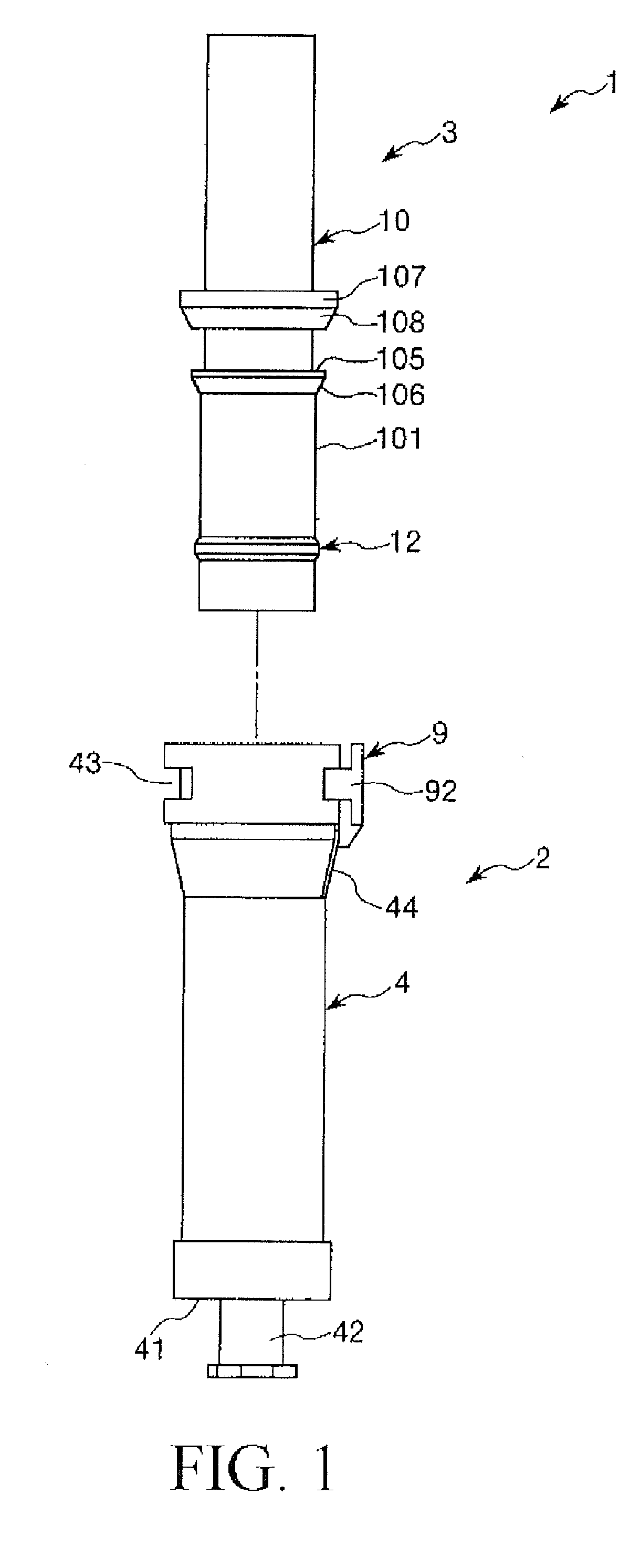
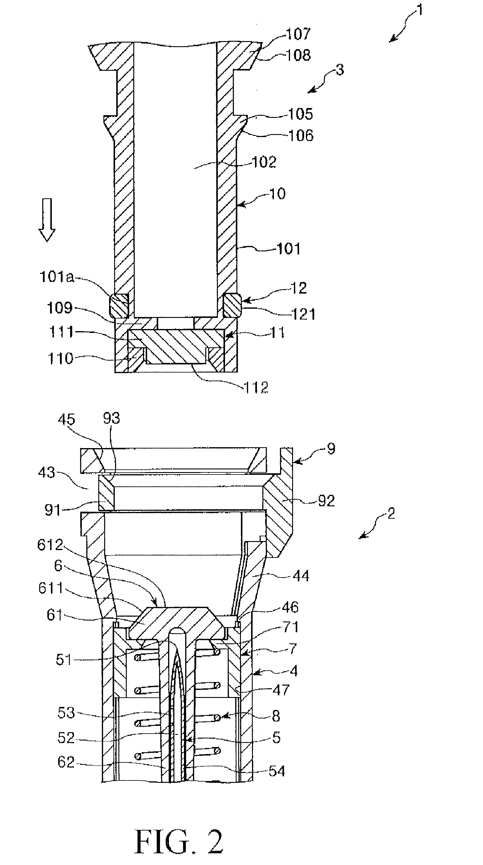
[0078]FIG. 1 is an exploded side view of a connector assembly (first embodiment) according to the present invention; FIGS. 2 to 4 are longitudinal sectional views illustrating a process until a first connector and'a second connector in the connector assembly according to the present invention are brought into an assembled state (mounted state); FIGS. 5 to 7 are longitudinal sectional views illustrating a process until the connector assembly (in the assembled state) shown in FIG. 4 is brought into a disassembled state; FIG. 8 is a longitudinal sectional view illustrating the first connector of the connector assembly (first embodiment) according to the present invention; FIG. 9 is a longitudinal sectional view illustrating the second connector of the connector assembly (first embodiment) according to the present invention; and FIG. 18 is a partial longitudinal sectional view illustrating a syringe which is mounted to the first connector shown in FIG. 8. Incidentally, in the following ...

second embodiment

[0160]FIG. 10 is a side view illustrating a second connector in a connector assembly (second embodiment) according to the present invention, and FIG. 11 is a cross sectional view illustrating a first connector body and a second connector body in an assembled state in the connector assembly (second embodiment) of the present invention.

[0161]Now, the second embodiment of the connector assembly according to the present invention will be described below, referring to these figures. The following description will be centered on the difference of the present embodiment from the above-described embodiment, and descriptions of the same items as above will be omitted.

[0162]The present embodiment is the same as the above-described first embodiment, except for a difference in the constitution of the second connector body.

[0163]A second connector body 10A shown in FIGS. 10 and 11 is integrally provided with six ribs 13 formed along the longitudinal direction at its outer peripheral portion 101....

third embodiment

[0167]FIG. 12 is a partial longitudinal sectional view illustrating a first connector body and a second connector body in a connector assembly (third embodiment) according to the present invention.

[0168]Now, the third embodiment of the connector assembly according to the present invention will be described below, referring to the figure. The following description will be centered on a difference from the above-described embodiments, and descriptions of the same items as above will be omitted.

[0169]The present embodiment is the same as the above-described first embodiment, except for differences in the constitutions of the first connector body and the second connector body.

[0170]As shown in FIG. 12, a first connector body 4B is formed with four spiral grooves 48 in its inner peripheral portion 47. In addition, a second connector body 10B is projectingly provided with four projections 14 at a proximal end portion of an outer peripheral portion 101 thereof. At the time of obtaining an ...


PUM


Abstract

A connector assembly is provided with a first connector equipped with a first connector body, a hollow needle supported on the inner side of the first connector body and having a side hole (53), and a first sealing member having a head which can be pierced through by the hollow needle; a second connector equipped with a second connector body and also with a second scaling member which can, when in a mounted state, be pierced through by the hollow needle; and a close-contact maintaining means which can, when in the mounted state, maintain that the head and the second sealing member are in close contact with each other. When the second connector becomes pulled out of the first connector, the head and the second sealing member are held in close contact with each other by the close-contact maintaining means until the hollow needle is pulled out of the second scaling member.

Description

TECHNICAL FIELD [0001]The present invention relates to a connector assembly.BACKGROUND ART [0002]Normally, a medical agent which is dangerous if a medical care worker touches it by mistake, such as carcinostatics, immunosuppressants, etc. is contained in a powdery state in a vial container (medical agent container) having a mouth part sealed with a rubber stopper.[0003]In taking the medical agent out of such a vial container, operations as follows are carried out.[0004]First, the mouth part of the vial container and a mouth part of a syringe into which a dissolving liquid has been portioned out are connected to each other through a connector (see Patent Document 1). Next, in this connected condition, the dissolving liquid is injected from the syringe into the vial container. Then, the medical agent is uniformly dissolved in the dissolving liquid by such an operation as a pumping operation or shaking of the vial container. Subsequently, the dissolving liquid with the medical agent di...

Claims


Application Information

Patent Timeline
Patent Type & Authority Applications(United States)
IPC IPC(8): A61J1/20
CPCA61J1/2096A61J2001/201A61J2001/2051A61M5/162A61M2039/267A61M39/0606A61M39/1011A61M2039/1072A61M2039/1077A61M39/04A61J1/201A61J1/2051
Inventor HIRANUMA, TAKAAKITAKEMOTO, MASAFUMIOKABE, HIROMITSU
Owner TERUMO KK
Why Eureka
Try Eureka