Rotatable tool for chip removing machining as well as a loose top and a basic body therefor

Inactive Publication Date: 2011-05-12
SANDVIK INTELLECTUAL PROPERTY AB
View PDF20 Cites 36 Cited by
  • Summary
  • Abstract
  • Description
  • Claims
  • Application Information

AI Technical Summary

Problems solved by technology

Previously known drills of the type that requires axial movement of the loose top into and out of a downwardly open jaw in the basic body, present in this respect annoying problems for the operator.
However, the drill is often situated deep inside the machine, and therefore the operator has to lean or bend far in over the subjacent table.
However, such compromises are most unsatisfactory, not only in respect of the ergonomics of the operator, but also in respect of t

Method used


Image

  • Rotatable tool for chip removing machining as well as a loose top and a basic body therefor
  • Rotatable tool for chip removing machining as well as a loose top and a basic body therefor
  • Rotatable tool for chip removing machining as well as a loose top and a basic body therefor

Examples


Embodiment Construction

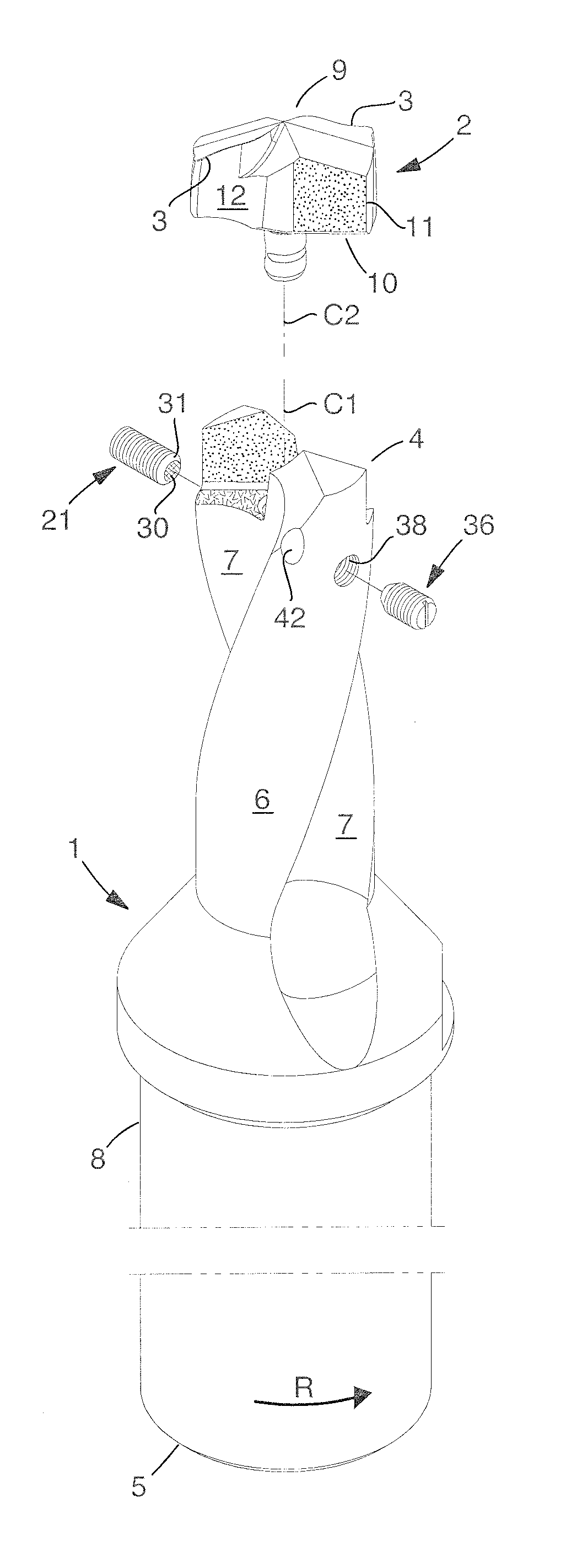
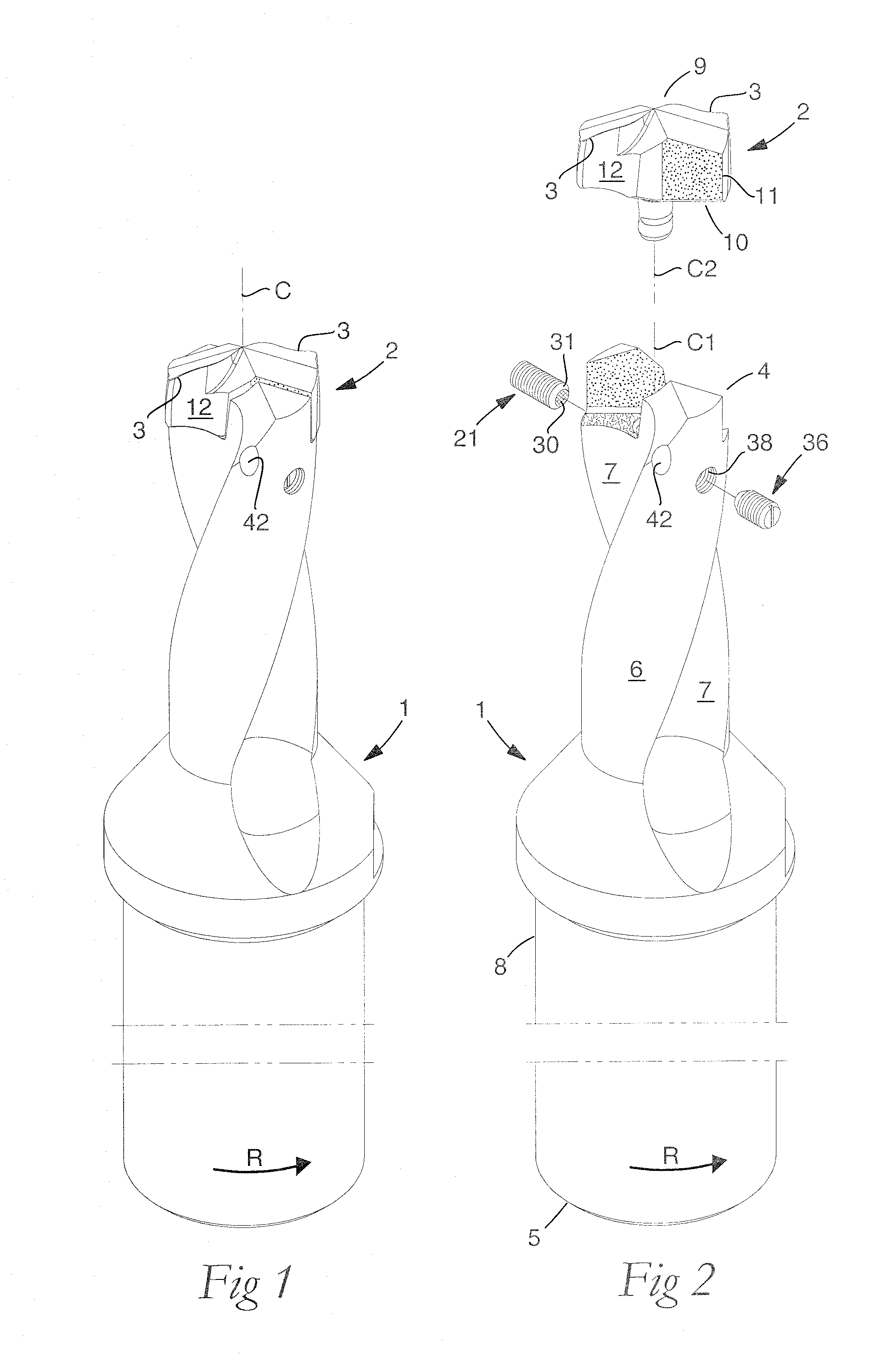
[0019]In the drawings, the invention has been exemplified in the form of drilling tools in two different embodiments, viz. a first embodiment according to FIGS. 1-5 and a second one according to FIG. 6. The drilling tool shown in FIGS. 1 and 2 includes a basic body 1 and a loose top 2 in which the requisite cutting edges 3 are included. In its composed, operative state according to FIG. 1, the tool is rotatable around a center axis designated C, more precisely in the direction of rotation R. In FIG. 2, it is seen that the basic body 1 includes front and rear ends 4, 5 between which a center axis C1 specific to the basic body extends. In the backward direction from the front end 4, a cylindrical envelope surface 6 extends in which two chip flutes 7 are countersunk, which in this case are helicoidal, but which also may be straight. In the example, the chip flutes 7 end in a collar included in a rear part 8 intended to be attached in the driving holder of the drilling machine in questi...


PUM


Abstract

A rotatable tool for chip removing machining, including a basic body having front and rear ends between which a first center axis extends with which an envelope surface is concentric, the front end including a jaw delimited by two torque-transferring drivers and an intermediate bottom in which a center hole extending axially inside the basic body mouths, and a bore for a locking screw extending radially between the center hole and the envelope surface. A loose top has front and rear ends between which a second center axis extends, in the extension of which a pin protruding from the rear end extends that is delimited by a free end surface and an envelope surface in which a shoulder surface is included for the locking screw arranged in the radial bore. A countersink axially spaced apart from the end surface is formed in the envelope surface of the pin of the loose top for the receipt of a snap-in member arranged along the inside of the center hole to provisionally clamp the pin in the center hole when the locking screw is not tightened.

Description

[0001]This application claims priority under 35 U.S.C. §119 to Swedish Patent Application No. 0950850-8, filed on Nov. 10, 2009, which is incorporated by reference herein in its entirety.FIELD OF THE INVENTION[0002]The present invention relates generally to a rotatably tool for chip removing machining of the type that includes, on one hand, a basic body having front and rear ends between which a first center axis extends with which an envelope surface is concentric, the front end including a jaw delimited by two torque-transferring drivers and an intermediate bottom in which a center hole extending axially inside the basic body mouths, and a bore for a locking screw extending radially between the center hole and the envelope surface, and on the other hand a loose top that includes front and rear ends between which a second center axis extends, in the extension of which a pin protruding from the rear end extends that is delimited by a free end surface and an envelope surface in which...

Claims


Application Information

Patent Timeline
IPC IPC(8): B23B51/00
CPCB23B31/1076B23B51/02Y10T408/892B23B2251/50B23B2251/02B23B51/00B23C5/22B23C5/24B23B51/0004B23B2205/04B23C5/2472
Inventor FRISENDAHL, JORGEN
Owner SANDVIK INTELLECTUAL PROPERTY AB
Why Eureka
Try Eureka