RF transition with 3-dimensional molded RF structure

a three-dimensional molded, radio frequency technology, applied in the direction of multiple-port networks, electrical devices, waveguides, etc., can solve the problem of new challenges for transmission lines on those antennas

Active Publication Date: 2011-05-19
RAYTHEON CO
View PDF27 Cites 18 Cited by
  • Summary
  • Abstract
  • Description
  • Claims
  • Application Information

AI Technical Summary

Problems solved by technology

As the next generation antennas are designed, new challenges for transmission lines on those antennas are presented.

Method used


Image

  • RF transition with 3-dimensional molded RF structure
  • RF transition with 3-dimensional molded RF structure
  • RF transition with 3-dimensional molded RF structure

Examples


Embodiment Construction

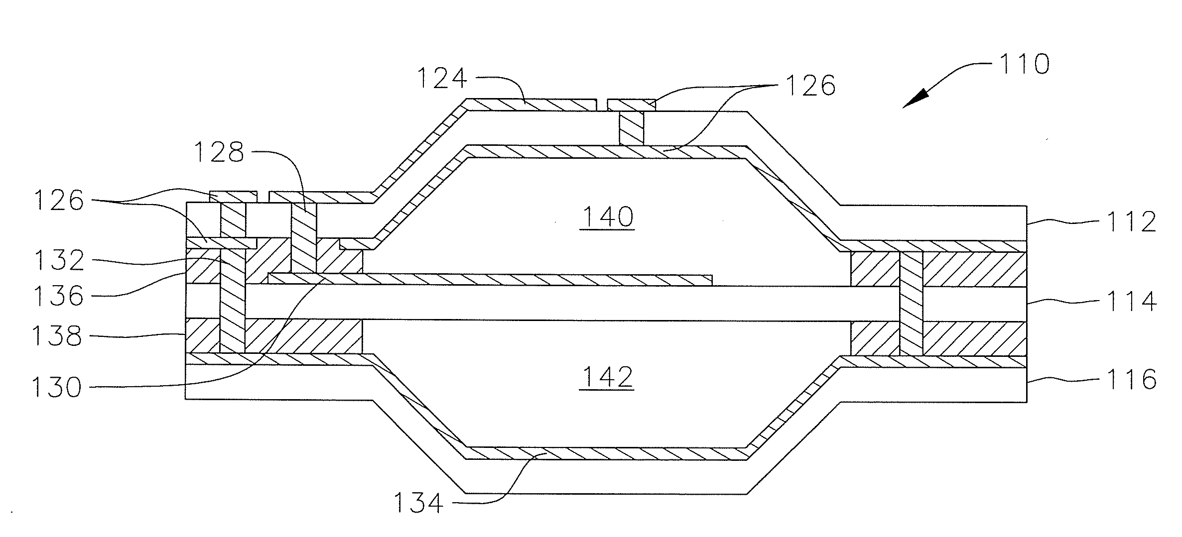
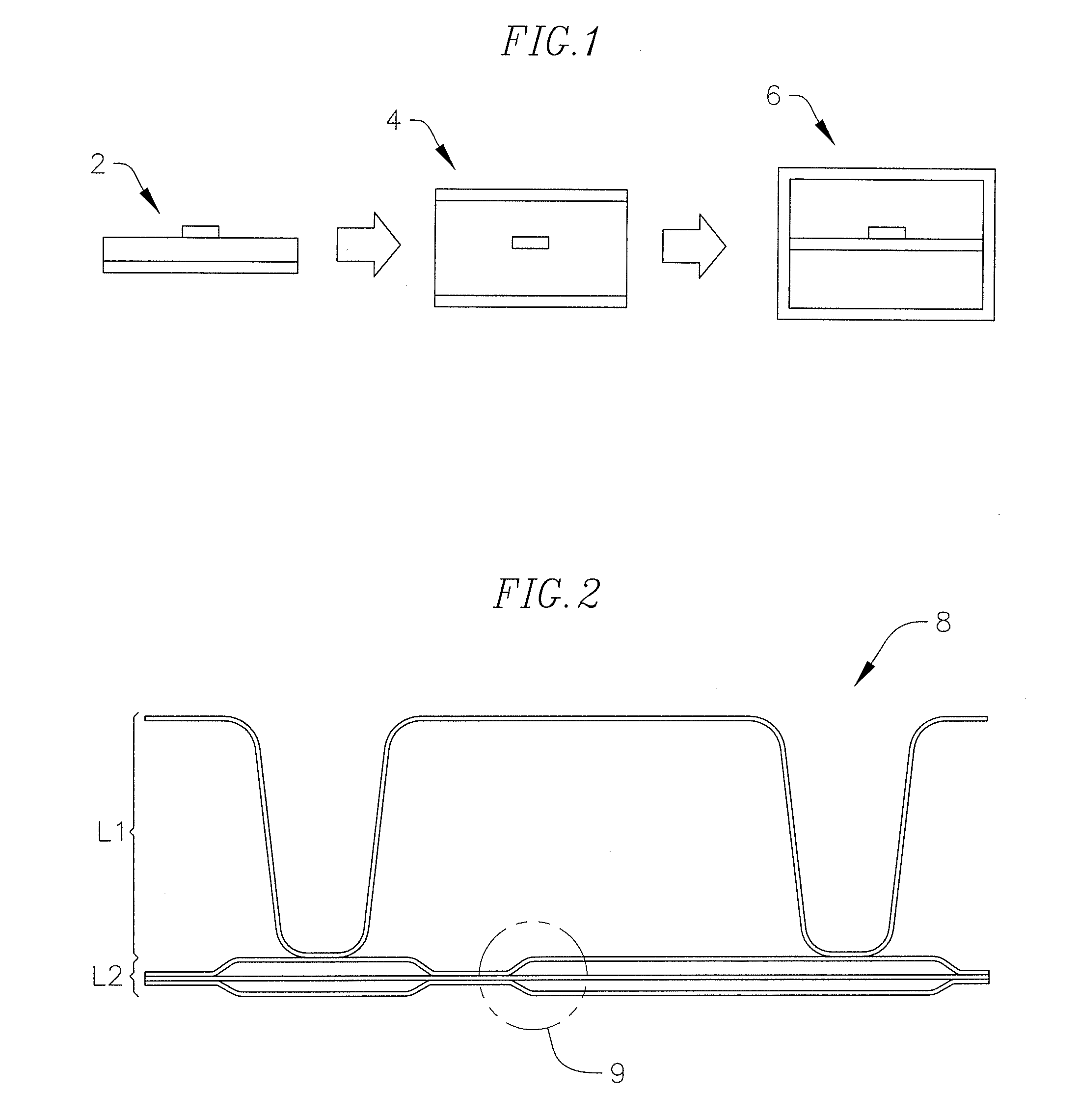
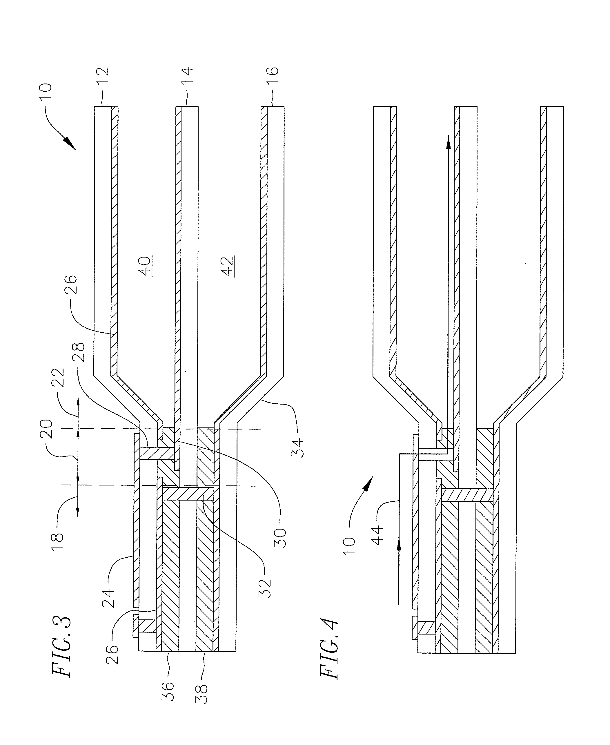
[0016]Referring now to the drawings, embodiments of RF transitions / assemblies are illustrated. The RF transitions / assemblies provide a transition from a first transmission line such as microstrip to a second transmission line such as suspended substrate stripline. In a number of embodiments, the transitions include an intermediate transmission line such as dielectric stripline. Many embodiments of the RF transitions include an assembly having a first flexible layer, a second flexible layer and a third flexible layer. In such case, a first section of the assembly can provide a microstrip transmission line, a second section of the assembly can provide a dielectric stripline transmission line, and a third section of the assembly can provide a suspended substrate stripline transmission line. These sections can run in sequence such that the second section is after the first section and the third section is after the second section, thereby providing a transition from microstrip to dielec...


PUM


Abstract

A radio frequency (RF) transition for a three dimensional molded RF structure is provided. In one embodiment, the invention relates to a radio frequency (RF) transition for an RF structure, the RF transition includes an assembly having a first flexible layer, a second flexible layer, and a third flexible layer, wherein a first section of the assembly includes a microstrip transmission line, wherein a second section of the assembly includes a dielectric stripline transmission line, and wherein a third section of the assembly includes a suspended substrate stripline transmission line.

Description

STATEMENT REGARDING FEDERALLY SPONSORED RESEARCH[0001]This invention was made with Government support from the Defense Advanced Research Projects Agency (DARPA) for the Integrated Sensor Is Structure (ISIS) program and under contract number FA8750-06-C-0048. The U.S. Government has certain rights in this invention.BACKGROUND[0002]The present invention relates generally to a radio frequency (RF) transition for a three dimensional molded RF structure. More specifically, the invention relates to an RF transition from a microstrip transmission line to a suspended substrate transmission line used in conjunction with the RF structure.[0003]Next generation large area multifunction active arrays for applications such as space and airborne based antennas need to be lighter weight, lower cost and more conformal than what can be achieved with current active array architecture and multilayer active panel array development. These space and airborne antennas can be used for radar and communicatio...

Claims


Application Information

Patent Timeline
Patent Type & Authority Applications(United States)
IPC IPC(8): H01P3/08
CPCH01Q1/36H01P5/04
Inventor QUAN, CLIFTONYANG, FANGCHOUKIM, HEE KYUNGVISCARRA, ALBERTO F.
Owner RAYTHEON CO
Why Eureka
Try Eureka