System and method for detection of a temperature on a surface of a body

Inactive Publication Date: 2011-05-19
LINDNER BJOERN +2
View PDF2 Cites 39 Cited by
  • Summary
  • Abstract
  • Description
  • Claims
  • Application Information

AI Technical Summary

Benefits of technology

In an embodiment of the invention, a VIS image can be created in the method of the specific area of the body surface with subsequently the transformed 2D information of the data record generated by the analyzing unit being linked to the VIS image so that exclusively such pixels of the VIS image are selected which correspond to the 3D information of the data record. Generation of a VIS image, which can represent a usual grayscale or colored picture, facilitates for an operator (for example a medical practitioner) perception of the recording of the specific area of the body surface.
In an embodiment of the invention, in the method by means of an image processing algorithm in the specific area of the body surface a specific temperature pattern in the form of an Object-of-Interest (OOI) is identified. An 001 may be a decubitus wound with its characteristic temperature zones. The image

Problems solved by technology

This linking results in the fact that for analysis of the thermal image only such pixels are selected, which ar

Method used


Image

  • System and method for detection of a temperature on a surface of a body
  • System and method for detection of a temperature on a surface of a body
  • System and method for detection of a temperature on a surface of a body

Examples


Embodiment Construction

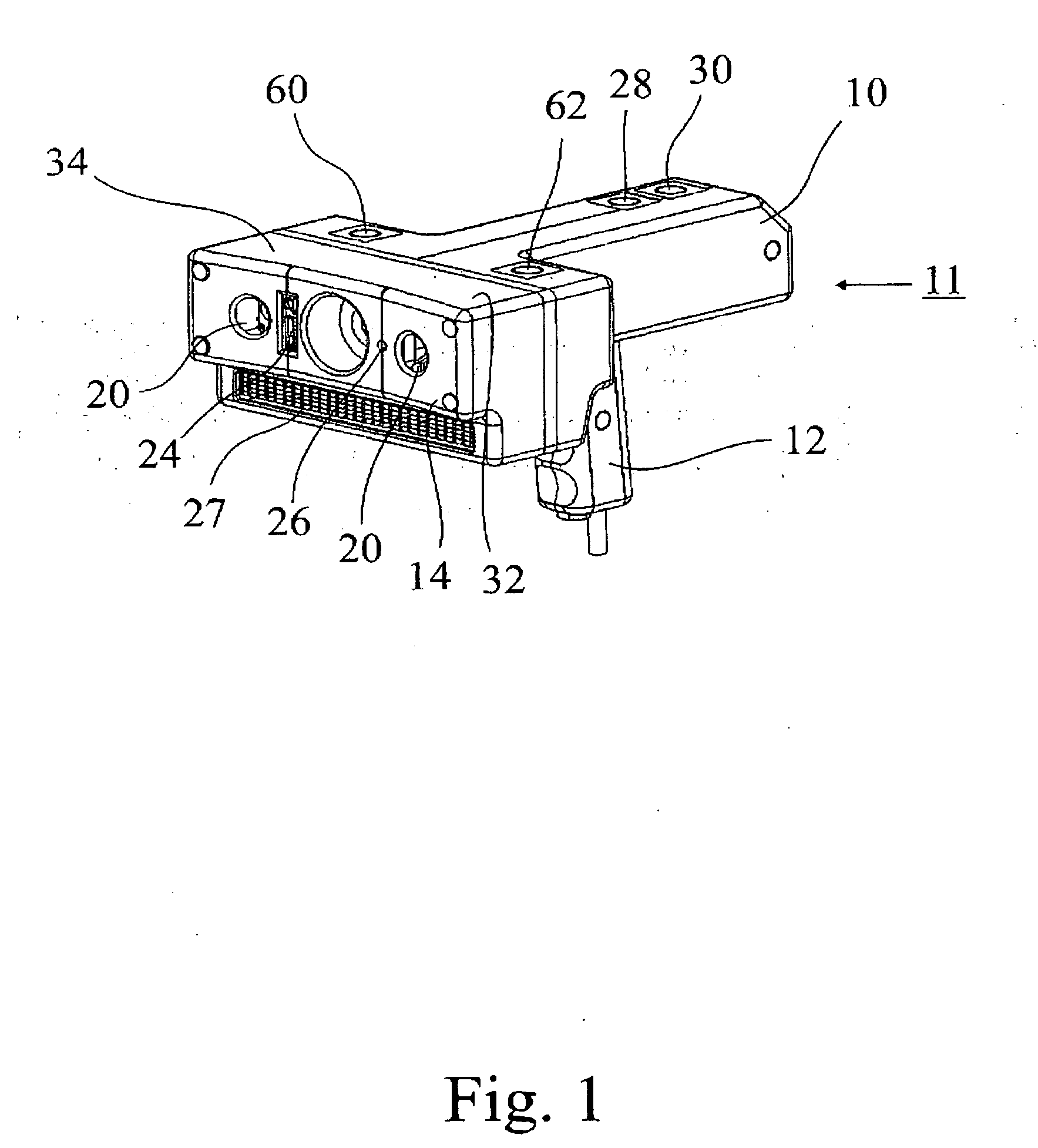
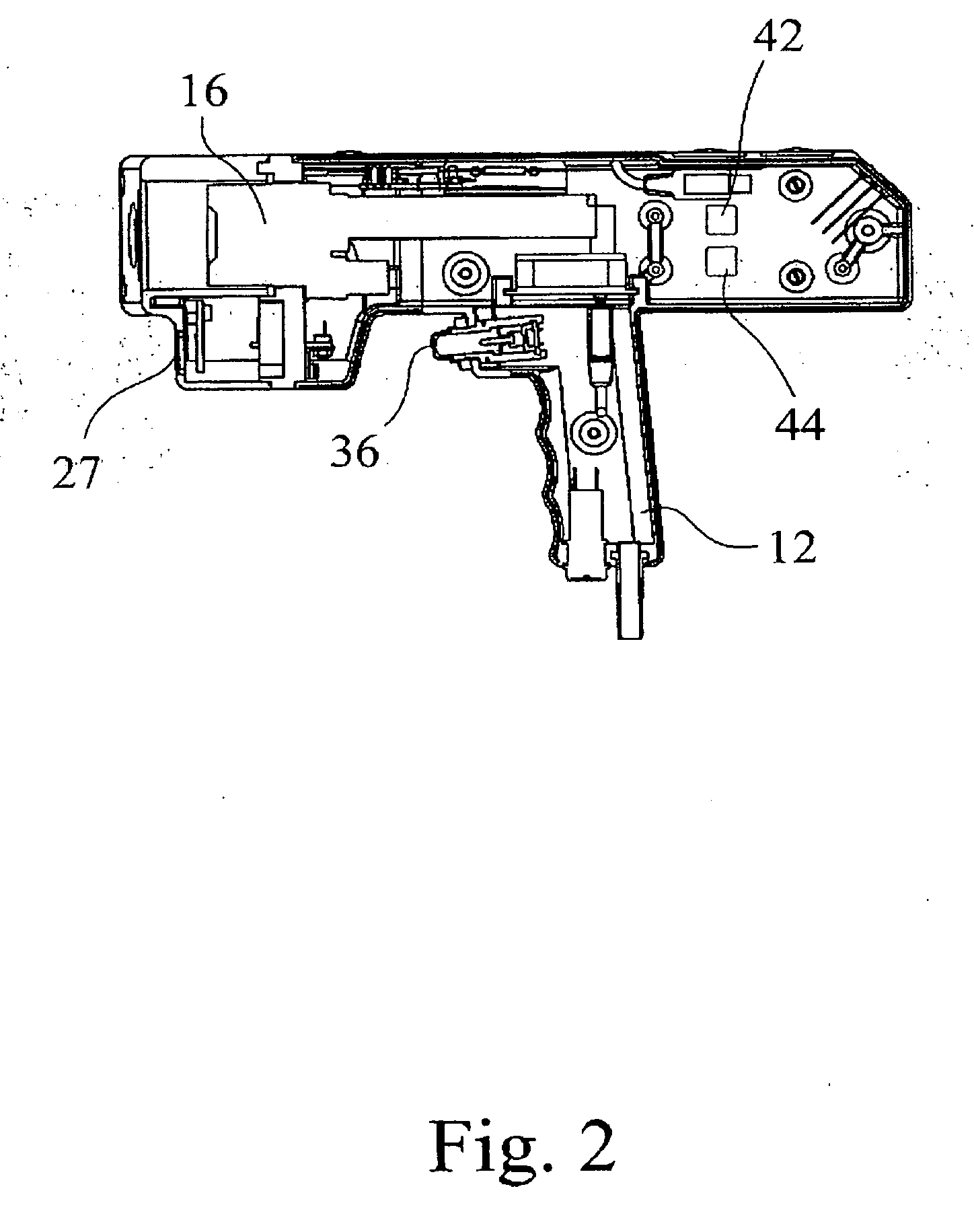
FIG. 1 is a perspective view of a housing 10 accommodating some important components of an inventive system. The housing 10 is of compact design and can be easily handled by hand by an operator. For this, a grip area 12 is formed at the bottom of the housing 10.

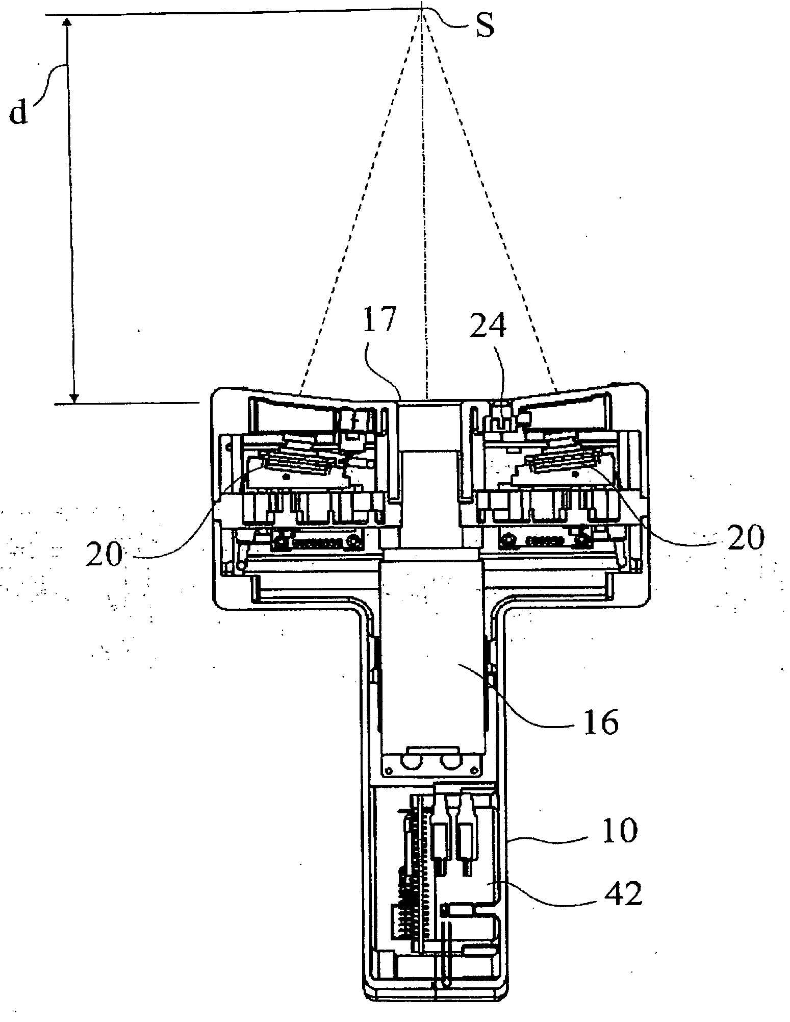
The housing 10 comprises a front face 14 which during an examination is oriented towards a surface of a body to be examined. On the front face 14 a thermal image camera 16 in the form of an IR camera is located in a central area. This thermal image camera 16 is to be understood as a first IR camera system 18. Contrary to the embodiment shown in FIG. 1, the first IR camera system 18 may also comprise a plurality of thermal image cameras 16. Moreover, one stereo camera 20 each is located on the border areas of the front face 14 of the housing 10. The two stereo cameras 20 are part of a second camera system 22. Further, an optical distance sensor 24 and a light spot projector 26 are provided on the front face 14. The optical dis...


PUM


Abstract

A system and method for detection of a temperature on a surface of a body is provided. The system includes a first IR camera system via which the temperature of a certain area of the surface is detectable in the form of a thermal image; a second camera system via which three-dimensional information is detectable regarding a position of a specific area of the body surface related to the first IR camera system; at least a first database in which at least for one body a corresponding model is stored by which at least one contour of the body is defined; and an analyzing unit connectable with the first database receiving the thermal image detected by the first IR camera system and the 3D information detected by the second camera system. Whereby the analyzing unit correlates the 3D information detected by the second camera system with a selectable model stored in the first database thereby generating a data record, which contains exclusively 3D information allocated to the model, the 3D information of the data record subsequently being transformed into a 2D space, and wherein the transformed 2D information of the generated data record is linkable to the thermal image so that exclusively such pixels of the thermal image are selected corresponding to the 2D information of the data record.

Description

This nonprovisional application claims priority under 35 U.S.C. §119(a) to German Patent Application No. DE 102009040017, which was filed in Germany on Sep. 9, 2009, and which is herein incorporated by reference.BACKGROUND OF THE INVENTION1. Field of the InventionThe present invention relates to a system and method for detection of a temperature on a surface of a body of any shape whatsoever, in particular for recognition of decubitus wounds on the human body or for recognition of temperature increases within the scope of an infectious and / or virus disease, for example in the event of a H1N1 or H5N1 infection.2. Description of the Background ArtIn many fields it is important to detect the temperature on the surface of technical devices, machines, industrial plants or buildings. The same applies to the examination of human or animal bodies where areas of different temperature may occur on the skin, in particular if sore locations have formed.On the human body, decubitus wounds occur ...

Claims


Application Information

Patent Timeline
IPC IPC(8): A61B6/00
CPCA61B5/015A61B5/445A61B5/4842G01J5/0022G01J5/0025G01J5/02G01J2005/0077G01J5/0265G01J5/0275G01J5/08G01J5/0846G01J5/0896G01J5/025
Inventor LINDNER, BJOERNPHILIPPS, JUERGENBEAUJEAN, RENE
Owner LINDNER BJOERN
Why Eureka
Try Eureka