
Multi-color indicator lighting

a multi-color indicator and light source technology, applied in the field of electric lighting, can solve the problems of reducing the intensity of light that otherwise would pass through the translucent lens, pcb material complicating the manufacturing process, and correct mounting of many leds on some substrates

Active Publication Date: 2011-06-02
DR LED HLDG
View PDF4 Cites 25 Cited by
  • Summary
  • Abstract
  • Description
  • Claims
  • Application Information

AI Technical Summary

Problems solved by technology

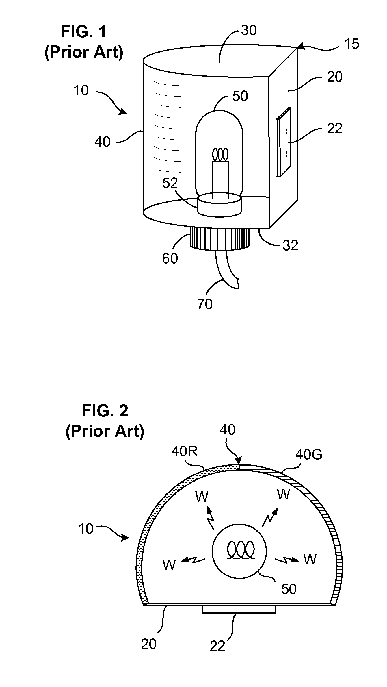
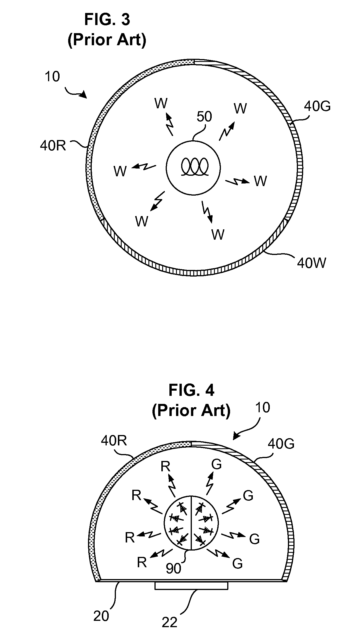
This makes it possible to use a single light source 50 (one or maybe even more bulbs or other light-emitting elements) yet still have light of different desired colors from a single light, but it also carries a clear disadvantage: To filter out unwanted wavelengths also means to reduce the intensity of the light that otherwise would pass through the translucent lens 40.
One disadvantage of this arrangement is that correct mounting of the many LEDs on some substrate such as PCB material complicates the manufacturing process—each LED will require two solder joints, one for each electrode, and also must be correctly aligned so as to shine in the intended direction.
Moreover, the substrate often has a complicated shape, such as being cylindrical or different planes, etc.
To prevent misdirection and waste of light, each group of LEDs may also be provided with—usually mounted within—a dedicated backing reflector (analogous to a standard flashlight or car headlight reflector) that aims their light according to a desired pattern; this further complicates the manufacturing process.

Method used


Image

  • Multi-color indicator lighting
  • Multi-color indicator lighting
  • Multi-color indicator lighting

Examples


Embodiment Construction

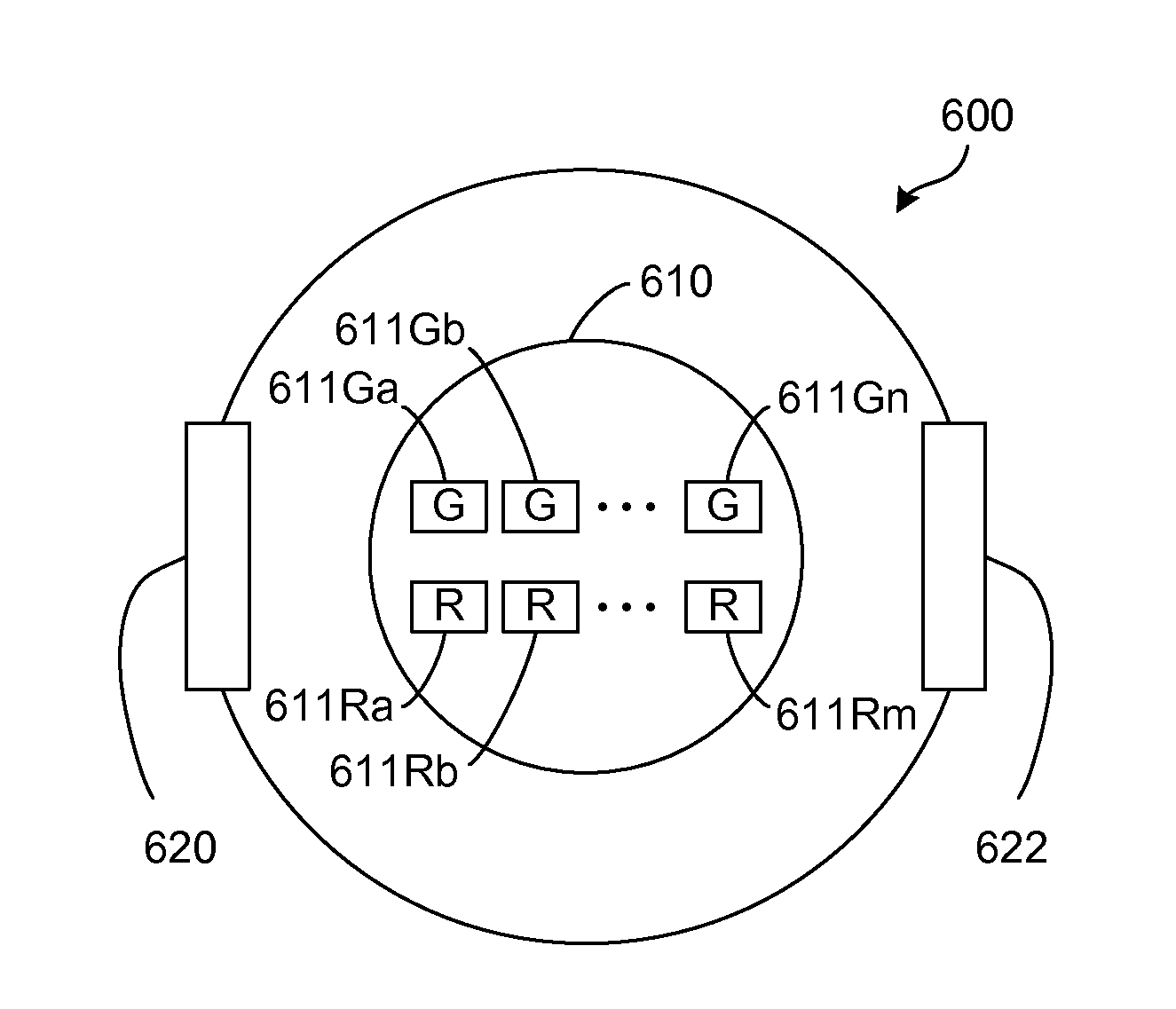
[0026]Various aspects of the invention are described below primarily using the example of a multi-color light suitable for use in a maritime environment, such that the example could be used to replace and improve upon the lights shown in FIGS. 1-4. This is purely by way of example and ease of explanation. Structural elements shown in FIGS. 1-3 that may also be used in embodiments of this invention are referred to below with the same reference numbers in FIG. 7.

[0027]One advantage of using this environment as an example is that it is particularly demanding. Nonetheless, marine lighting is only one area in which the different aspects of the invention will be useful—as both users and skilled lighting designers will appreciate, the improvements provided by this invention may be applied to other situations as well in which it is desired to have efficient multi-color indicator lighting.

[0028]FIG. 5 illustrates a common LED “package”500 containing multiple, possibly differently colored “di...


PUM


Abstract

A light for multi-color indication, for example, as navigation light, has a light source with a plurality of LEDs on a common substrate, within a common package and a common package lens. The LEDs may be of different colors. A reflector may be mounted opposite the light source to direct “mixed-color” light through differently colored portions of a casing lens. A reflective surface of the reflector may be shaped substantially as a surface of rotation. A reflective material such as a film may be positioned on the casing lens to extend over at least part of an angular range of any of the lens portion(s) corresponding to an unneeded light color, so as to reflect incident light towards a selected one of the lens portions corresponding to a needed light color.

Description

FIELD OF THE INVENTION[0001]This invention relates in general to electric lighting and more particularly to lighting that uses different colors to indicate, for example, the nature, status, position, orientation, etc., of the object bearing the lighting.BACKGROUND OF THE INVENTION[0002]Differently colored lights have been used as indicators for a very long time. Sometimes, colors indicate absolute or relative position, such as that a viewer is in a “dangerous” as opposed to a “safe” sector. Every nighttime driver knows the difference between red tail lights and white headlights.[0003]As another example, in 1848 the United Kingdom began requiring certain ships to display red and green navigation sidelights on their port and starboard sides, respectively; this rule was adopted internationally in 1898. Nowadays, the International Regulations for Preventing Collisions at Sea 1972 (COLREGS) published by the International Maritime Organization (IMO) specify which lights of which colors ma...

Claims


Application Information

Patent Timeline
Patent Type & Authority Applications(United States)
IPC IPC(8): F21V9/00F21V7/00
CPCB63B45/04F21V7/0008F21Y2101/02F21V9/08F21W2101/04F21V7/09F21Y2115/10F21W2107/20
Inventor NG, JAMES K.
Owner DR LED HLDG
Learn More