Ventilator Respiratory Gas Accumulator With Dip Tube
Active Publication Date: 2011-06-09
TYCO HEALTHCARE GRP LP
View PDF100 Cites 134 Cited by
Summary
Abstract
Description
Claims
Application Information
AI Technical Summary
This helps you quickly interpret patents by identifying the three key elements:
Problems solved by technology
Method used
Benefits of technology
Benefits of technology
[0004]Some mixing vessels are not directly in the gas delivery flow path, but are instead removed from the gas flow path, such as in a “T” configuration, in order to reduce the amount of time necessary to deliver a change in gas mixture to a patient. In the “T” configuration, the gas flow path goes across the top of the “T” and the accumulator is connected to the flow path by the stem of the “T”. The stem of “T” separates the accumulator from the flow path. When in this configuration and during the changing of a gas mixture, a pocket of air from the accumulator may periodically get sucked into the gas flow path changing the gas mixture concentrations sent to the patient. This periodic pocket of air or “burp” of air in the gas flow path disrupts the desired gas mixture to the patient. Accordingly, while the an accumulator removed from the gas flow path may reduce the time necessary to deliver a change in gas mixture to the patient, it also results in intermittent burps or pockets of air that do not contain the desired gas mixture or gas concentrations during ventilation.SUMMARY
[0006]In part, this disclosure describes a method for ventilating a patient. The method includes providing a dip-tube, the dip-tube has a first end within an accumulator located away from the flow path and a second end connected to the flow path. A distance between the first end and the second end of the dip-tube is 10 inches to 14 inches long. Further, this distance reduces undesirable pockets of a gas mixture contained in the accumulator from entering the flow path to a patient circuit. The method further includes controlling a flow rate of the first gas mixture to keep a gas interface inside the dip-tube.
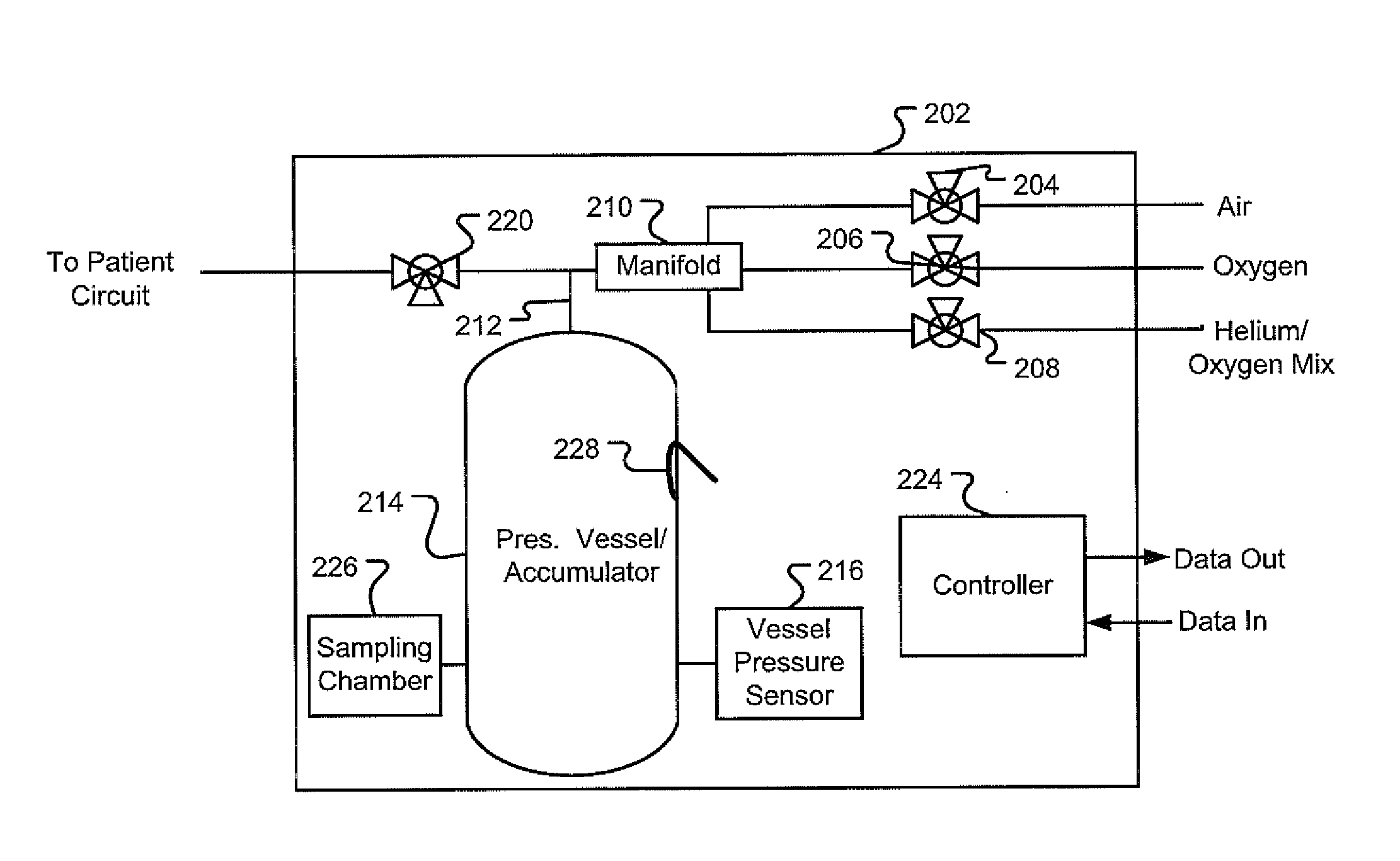
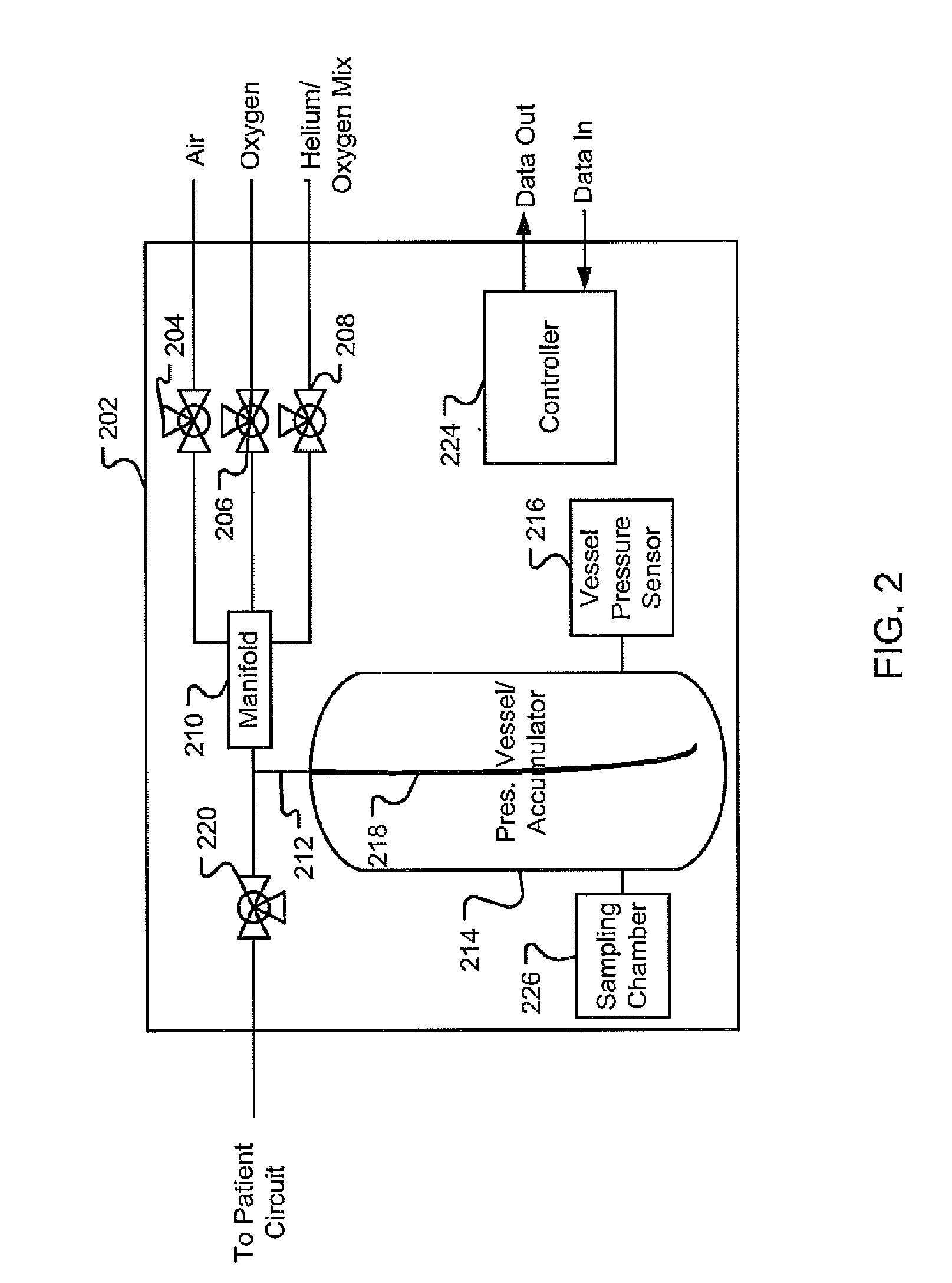
[0007]The disclosure also describes a medical ventilatorsystem. The medical ventilator system includes a processor; a plurality of sources of different gases controlled by the processor; a gas manifold connected to an outlet to a patient circuit via a flow path, the gas manifold receiving gas from the plurality of gas sources to form a gas mixture; and an accumulator connected to the flow path by a dip-tube. The dip-tube has a first end within the accumulator and a second end connected to the flow path and wherein the distance between the first end and the second end is a length selected to reduce undesirable pockets of the gas mixture contained in the accumulator from entering the outlet to the patient circuit.
[0008]In yet another aspect, the disclosure describes a pressure support system that includes: a processor; a pressure generating system controlled by the processor, the pressure generating system is adapted to generate a flow of breathing gas; a ventilation system including a patient circuit controlled by the processor; a plurality of sources of different gases controlled by the processor; a gas manifold connected to an outlet to a patient circuit via a flow path, the gas manifold receiving gas from the plurality of gas sources; and an accumulator connected to the flow path by a dip-tube. The dip-tube has a first end within the accumulator and a second end connected to the flow path and wherein the distance between the first end and the second end is a length selected to reduce undesirable pockets of the gas mixture contained in the accumulator from entering the outlet to the patient circuit.
Problems solved by technology
The elevated pressure of the gas mixture stored in the accumulator makes it prohibitively expensive to directly measure the concentrations of gas found within the accumulator using current gas mixture monitoring technology.
Accordingly, some systems provide conservative estimates of the time needed for a new gas mixture to replace an old gas mixture within the accumulator chamber during ventilation.
This periodic pocket of air or “burp” of air in the gas flow path disrupts the desired gas mixture to the patient.
Accordingly, while the an accumulator removed from the gas flow path may reduce the time necessary to deliver a change in gas mixture to the patient, it also results in intermittent burps or pockets of air that do not contain the desired gas mixture or gas concentrations during ventilation.
Method used
Image
Click on the blue label to locate the original text in one second.
Reading with bidirectional positioning of images and text.
Examples
examples
[0101]The accumulator acts as a buffer between flow in from the mix valves and flow out through the delivery module. This buffer slows down the rate of change of pressure in the mix module, which is helpful for valve control. Further, larger accumulators provide more of this benefit. However, when the gas mixture is changed, a larger accumulator increases the amount of time necessary to deliver the new gas mixture to the patient. Further, it is noted that the higher the flow rate, the faster the volume of the new gas mixture moves through the ventilator.
[0102]In order to determine how to delivery a change in gas mixture to a patient as quickly as possible, three accumulator styles were evaluated. The results from the three accumulator styles were also compared to a control ventilator with no accumulator. In order to evaluate the change in gas mixture a 2 liters per minute (LPM) constant flow for the smallest neonatal breath was utilized (an about 2 ml breath size). Further, the gas ...
PUM
Abstract
This disclosure describes systems and methods for ventilating a patient with a system that includes an accumulator for storing a gas mixture. The disclosure describes systems and methods for ventilating a patient with a system that includes an accumulator located away from the flow path that reduces or eliminates pockets or burps of an undesirable gas mixture from entering the gas flow path and reaching the patient after a gas mixture change. The disclosure also describes a novel approach for reducing or eliminating these air pockets of undesirable gas by utilizing a dip-tube.
Description
RELATED APPLICATIONS[0001]This application claims the benefit of U.S. Provisional Application No. 61 / 266431, filed Dec. 3, 2009, and entitled, “Ventilator Respiratory Variable-Sized Gas Accumulator”, which is hereby incorporated herein by reference. This application, also, claims the benefit of U.S. Provisional Application No. 61 / 266438, filed Dec, 3, 2009,and entitled, “Ventilator Respiratory Gas Accumulator with Sampling Chamber”, which application is hereby incorporated herein by reference. Additionally, this application claims the benefit of U.S. Provisional Application No. 61 / 266404, filed Dec. 3, 2009, and entitled, “Ventilator Respiratory Gas Accumulator with Dip-Tube”, which application is hereby incorporated herein by reference. Further, this application claims the benefit of U.S. Provisional Application No. 61 / 266419, filed Dec. 3, 2009, and entitled, “Ventilator Respiratory Gas Accumulator with Purge Valve”, which application is hereby incorporated herein by reference.INT...
Claims
Application Information
Patent Timeline
Application Date:The date an application was filed.
Publication Date:The date a patent or application was officially published.
First Publication Date:The earliest publication date of a patent with the same application number.
Issue Date:Publication date of the patent grant document.
PCT Entry Date:The Entry date of PCT National Phase.
Estimated Expiry Date:The statutory expiry date of a patent right according to the Patent Law, and it is the longest term of protection that the patent right can achieve without the termination of the patent right due to other reasons(Term extension factor has been taken into account ).
Invalid Date:Actual expiry date is based on effective date or publication date of legal transaction data of invalid patent.
