Ventilator Respiratory Gas Accumulator With Sampling Chamber
What is AI technical title?
AI technical title is built by Patsnap AI team. It summarizes the technical point description of the patent document.
a technology of respiratory gas accumulator and ventilation chamber, which is applied in the direction of respirator, valve, mechanical apparatus, etc., can solve the problems of affecting the desired gas mixture to the patient, affecting the patient's breathing, and reducing the time needed to achieve the desired gas mixture, reducing or eliminating pockets or burps, and reducing or eliminating air pockets
Active Publication Date: 2011-06-09
TYCO HEALTHCARE GRP LP
View PDF100 Cites 147 Cited by
Summary
Abstract
Description
Claims
Application Information
AI Technical Summary
This helps you quickly interpret patents by identifying the three key elements:
Problems solved by technology
Method used
Benefits of technology
Benefits of technology
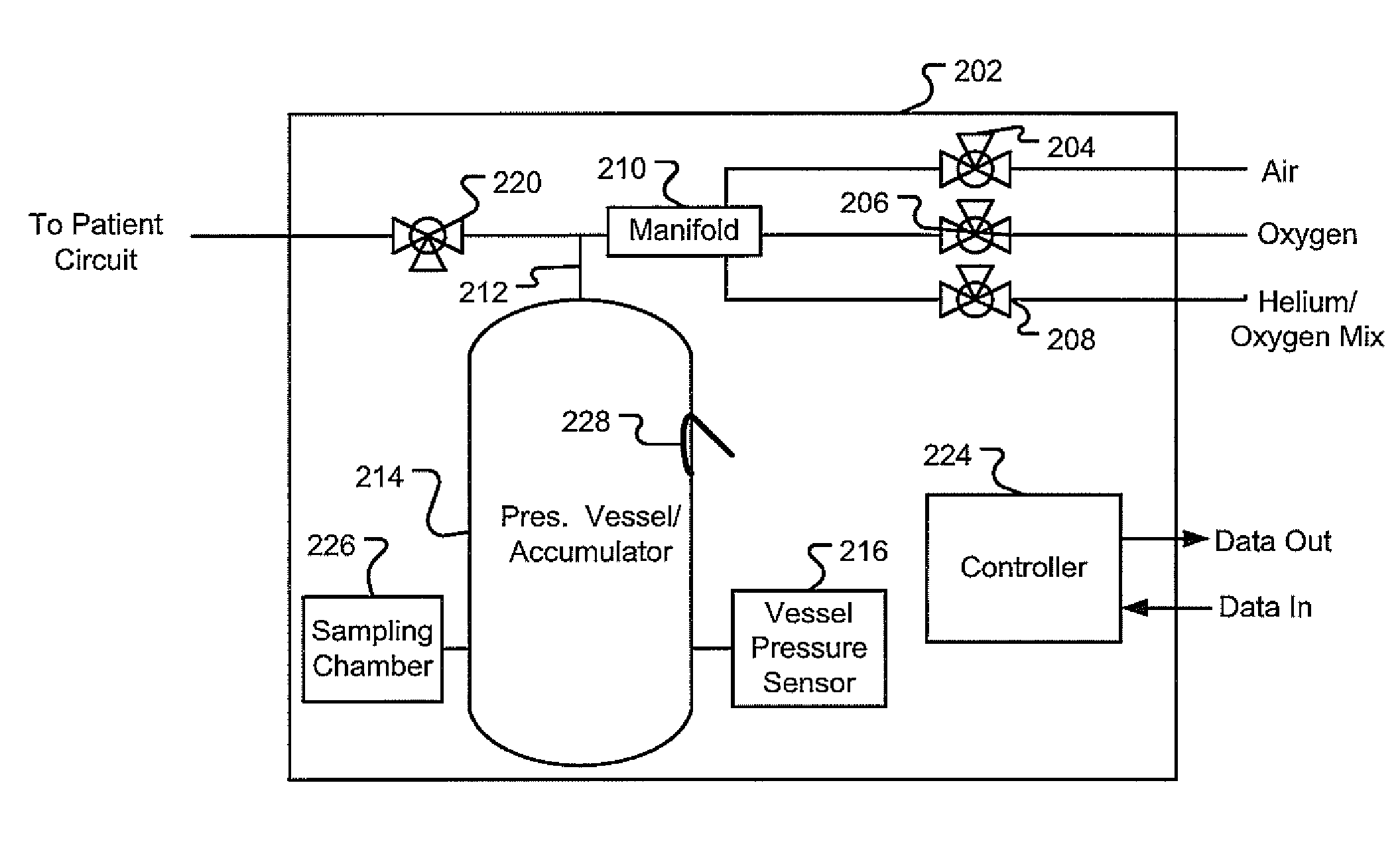
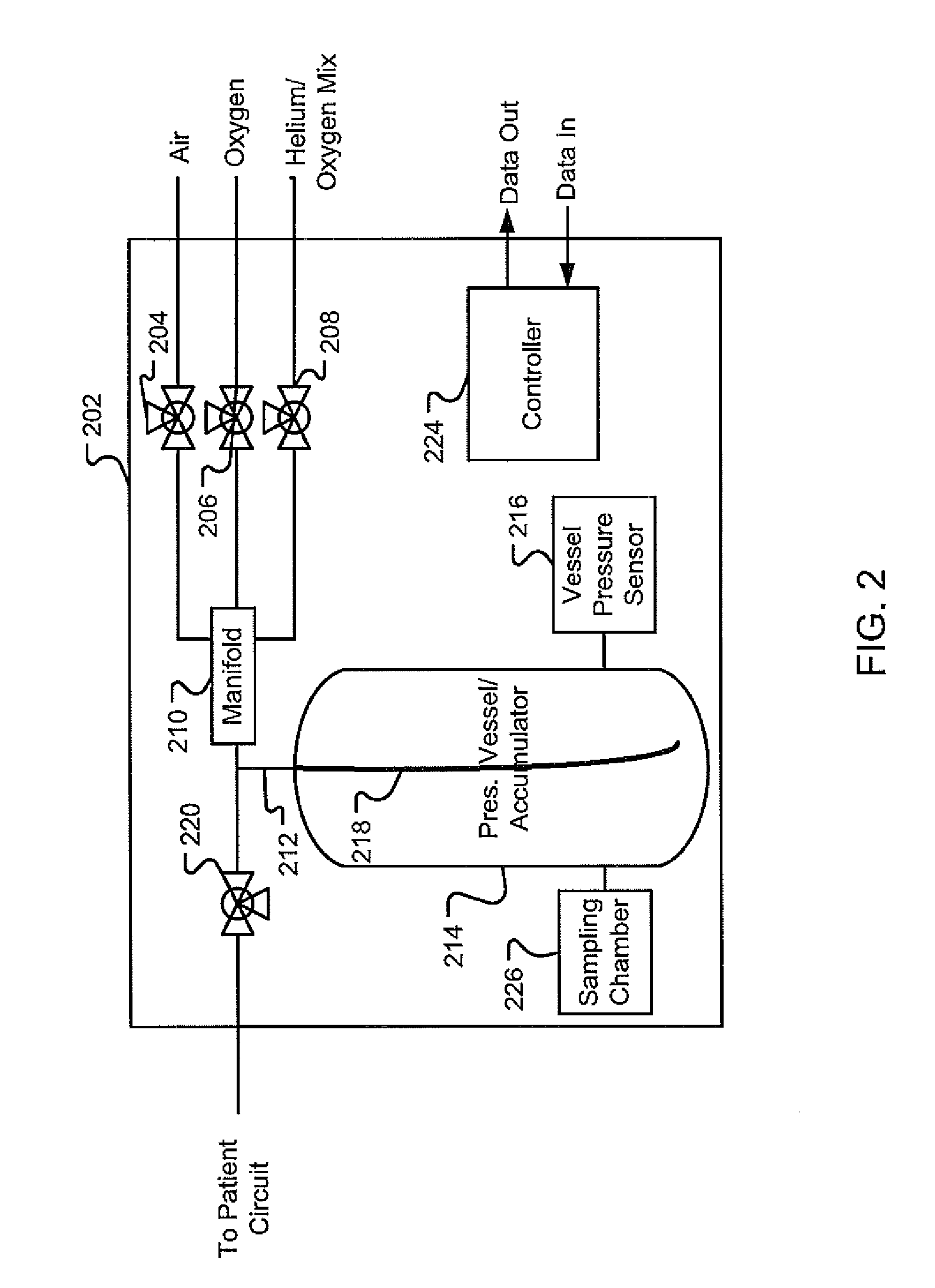
[0004]Some mixing vessels are not directly in the gas delivery flow path, but are instead removed from the gas flow path, such as in a “T” configuration, in order to reduce the amount of time necessary to deliver a change in gas mixture to a patient. In the “T” configuration, the gas flow path goes across the top of the “T” and the accumulator is connected to the flow path by the stem of the “T”. The stem of “T” separates the accumulator from the flow path. When in this configuration and during the changing of a gas mixture, a pocket of air from the accumulator may periodically get sucked into the gas flow path changing the gas mixture concentrations sent to the patient. This periodic pocket of air or “burp” of air in the gas flow path disrupts the desired gas mixture to the patient. Accordingly, while the an accumulator removed from the gas flow path may reduce the time necessary to deliver a change in gas mixture to the patient, it also results in intermittent burps or pockets of air that do not contain the desired gas mixture or gas concentrations during ventilation.SUMMARY
[0006]This disclosure also describes systems and methods for ventilating a patient with a system that includes an accumulator located away from the flow path that reduces or eliminates pockets or burps of an undesirable gas mixture from entering the gas flow path and reaching the patient after a gas mixture change. The disclosure describes a novel approach for reducing or eliminating these air pockets of undesirable gas by utilizing at least one of a dip-tube, a purge valve, and a variable size accumulator.
Problems solved by technology
The elevated pressure of the gas mixture stored in the accumulator makes it prohibitively expensive to directly measure the concentrations of gas found within the accumulator using current gas mixture monitoring technology.
Accordingly, some systems provide conservative estimates of the time needed for a new gas mixture to replace an old gas mixture within the accumulator chamber during ventilation.
This periodic pocket of air or “burp” of air in the gas flow path disrupts the desired gas mixture to the patient.
Accordingly, while the an accumulator removed from the gas flow path may reduce the time necessary to deliver a change in gas mixture to the patient, it also results in intermittent burps or pockets of air that do not contain the desired gas mixture or gas concentrations during ventilation.
Method used
Image
Click on the blue label to locate the original text in one second.
Reading with bidirectional positioning of images and text.
Examples
Embodiment Construction
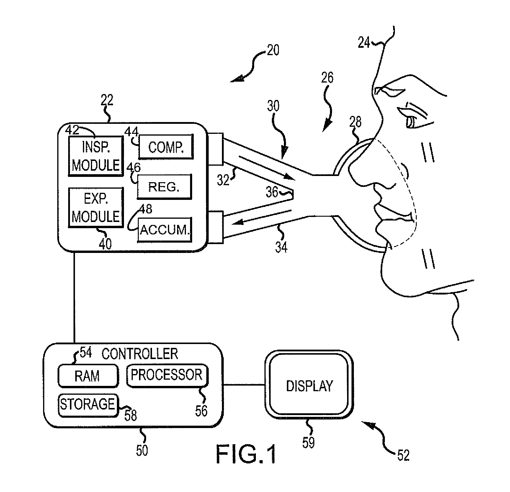
[0030]Although the techniques introduced above and discussed in detail below may be implemented for a variety of medical devices, the present disclosure will discuss the implementation of these techniques in the context of a medical ventilator for use in providing ventilation support to a human patient. The reader will understand that the technology described in the context of a medical ventilator for human patients could be adapted for use with other systems such as ventilators for non-human patients and general gas transport systems in which periodic gas mixture changes may be required. As utilized herein a “gas mixture” includes at least one of a pure gas and a mixture of pure gases.
[0031]Medical ventilators are used to provide a breathing gas to a patient who may otherwise be unable to breathe sufficiently. In modern medical facilities, pressurized air and oxygen sources are often available from wall outlets. Accordingly, ventilators may provide pressure regulating valves (or re...
PUM
Abstract
This disclosure describes systems and methods for ventilating a patient with a system that includes an accumulator for storing a gas mixture. The disclosure describes a novel approach for determining the concentrations of gas found in the accumulator by utilizing a sampling chamber. The disclosure further describes a novel approach for a fast delivery of a change in gas mixture to a patient by utilizing a variable-sized accumulator. This disclosure also describes systems and methods for ventilating a patient with a system that includes an accumulator located away from the flow path that reduces / eliminates pockets of an undesirable gas mixture from entering the gas flow path and reaching the patient after a gas mixture change by utilizing at least one of a dip-tube, a purge valve, and a variable size accumulator.
Description
RELATED APPLICATIONS[0001]This application claims the benefit of U.S. Provisional Application No. 61 / 266,431, filed Dec. 3, 2009, and entitled, “Ventilator Respiratory Variable-Sized Gas Accumulator”, which is hereby incorporated herein by reference. This application, also, claims the benefit of U.S. Provisional Application No. 61 / 266,438, filed Dec. 3, 2009, and entitled, “Ventilator Respiratory Gas Accumulator with Sampling Chamber”, which application is hereby incorporated herein by reference. Additionally, this application claims the benefit of U.S. Provisional Application No. 61 / 266,404, filed Dec. 3, 2009, and entitled, “Ventilator Respiratory Gas Accumulator with Dip-Tube”, which application is hereby incorporated herein by reference. Further, this application claims the benefit of U.S. Provisional Application No. 61 / 266,419, filed Dec. 3, 2009, and entitled, “Ventilator Respiratory Gas Accumulator with Purge Valve”, which application is hereby incorporated herein by referenc...
Claims
Application Information
Patent Timeline
Application Date:The date an application was filed.
Publication Date:The date a patent or application was officially published.
First Publication Date:The earliest publication date of a patent with the same application number.
Issue Date:Publication date of the patent grant document.
PCT Entry Date:The Entry date of PCT National Phase.
Estimated Expiry Date:The statutory expiry date of a patent right according to the Patent Law, and it is the longest term of protection that the patent right can achieve without the termination of the patent right due to other reasons(Term extension factor has been taken into account ).
Invalid Date:Actual expiry date is based on effective date or publication date of legal transaction data of invalid patent.

