Spout for a pouch

a technology for spouts and pouches, which is applied in the field of spouts for pouches, can solve the problems of contents leaking or deteriorating, possibly becoming so dirty, endangering health, etc., and achieves the effect of preventing a person from being damaged and maintaining sealing performan

Inactive Publication Date: 2011-06-09
KIM SANG SOON
View PDF18 Cites 16 Cited by
  • Summary
  • Abstract
  • Description
  • Claims
  • Application Information

AI Technical Summary

Benefits of technology

[0012]Accordingly, the present invention has been made keeping in mind the above problems occurring in the related art, and the present invention is intended to propose a spout for a pouch: in which a sealing end tube integrally formed with an outlet, through which contents are discharged, is safely protected by a protection cap so as to prevent the sealing end tube from breaking under an external force and resolve problems such as the contents leaking during the distribution of a product or deteriorating the packing stability and quality owing to the introduction of external air; in which the cap is so configured as to be spirally coupled with a body and if a person intends to discharge the contents, it is manipulated to be opened so that the sealing end tube is naturally decoupled from the outlet, thereby furthermore increasing convenience and reliability of the use of a product; and in which a sealing blade is provided in the cap so that the cap is repeatedly reused on the body in a sealed state.

Problems solved by technology

However, in the case of the spout using the aluminum sheet, there are the problems of an attaching process being further required and the spout possibly becoming so dirty as to endanger the health because an aluminum sheet is attached using an adhesive, and the contents maybe leaking or deteriorating when a product is distributed owing to a possible error occurring in the attachment or the introduction of external air.
Further, in the case of the skirt type spout in which the outlet is blocked by the rib, particularly upon high temperature sterilization, the problem of the sealed portion becoming thermally deformed so that it is impossible to prevent leaking of the contents or the introduction of external air occurs.
Apart from such problems, in the case of the spout A using the aluminum sheet, while the sealing performance is maintained when the contents have not yet been used, once the aluminum sheet is peeled off, although the outlet is sealed using the cap 4, a separate sealing means for blocking the outlet 2 is not provided, so that upon continuous and repeated using of the contents, sealing performance cannot still be expected.
Also, since it has a structure in which the outlet 2 is opened after decoupling the cap 4 and only then removing the sheet 3, it is impossible to completely prevent intentional forgery and falsification of the contents.
Furthermore, since the forgery-free skirt 5 is separately provided in the lower portion of the cap 4 in order to prevent forgery of the contents, it is very difficult to fabricate the spout, and thus the productivity is naturally degraded.
While such a spout structure can solve the problems occurring in the spout shown in FIGS. 1 and 2 to some degrees, since a cover for the dotted line is always exposed outside of the body, if the cover is occasionally opened in the distribution of a product, the dotted line is possibly broken so as to reduce the stability of the distribution and handling of a product, which deteriorates reliability of a product.
Therefore, the spout for a pouch according to the prior art has the drawbacks of being separately formed in order to conform to the use of high or low temperature sterilization, of there being a risk of leaking or deterioration of the contents when a product is distributed because it cannot resolve the problem of the outlet having to be blocked, and that even the cover structure, which is breakable from the outlet, can be exposed outside and thus possibly cause it to open owing to the occasional application of external force.

Method used


Image

  • Spout for a pouch
  • Spout for a pouch
  • Spout for a pouch

Examples


Embodiment Construction

[0043]Reference will now be made in greater detail to a preferred embodiment of the invention, an example of which is illustrated in the accompanying drawings. Wherever possible, the same reference numerals will be used throughout the drawings and the description to refer to the same or like parts.

[0044]FIGS. 3 to 13 illustrate the structure of a spout for a pouch according to the present invention.

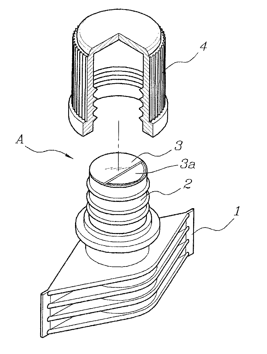
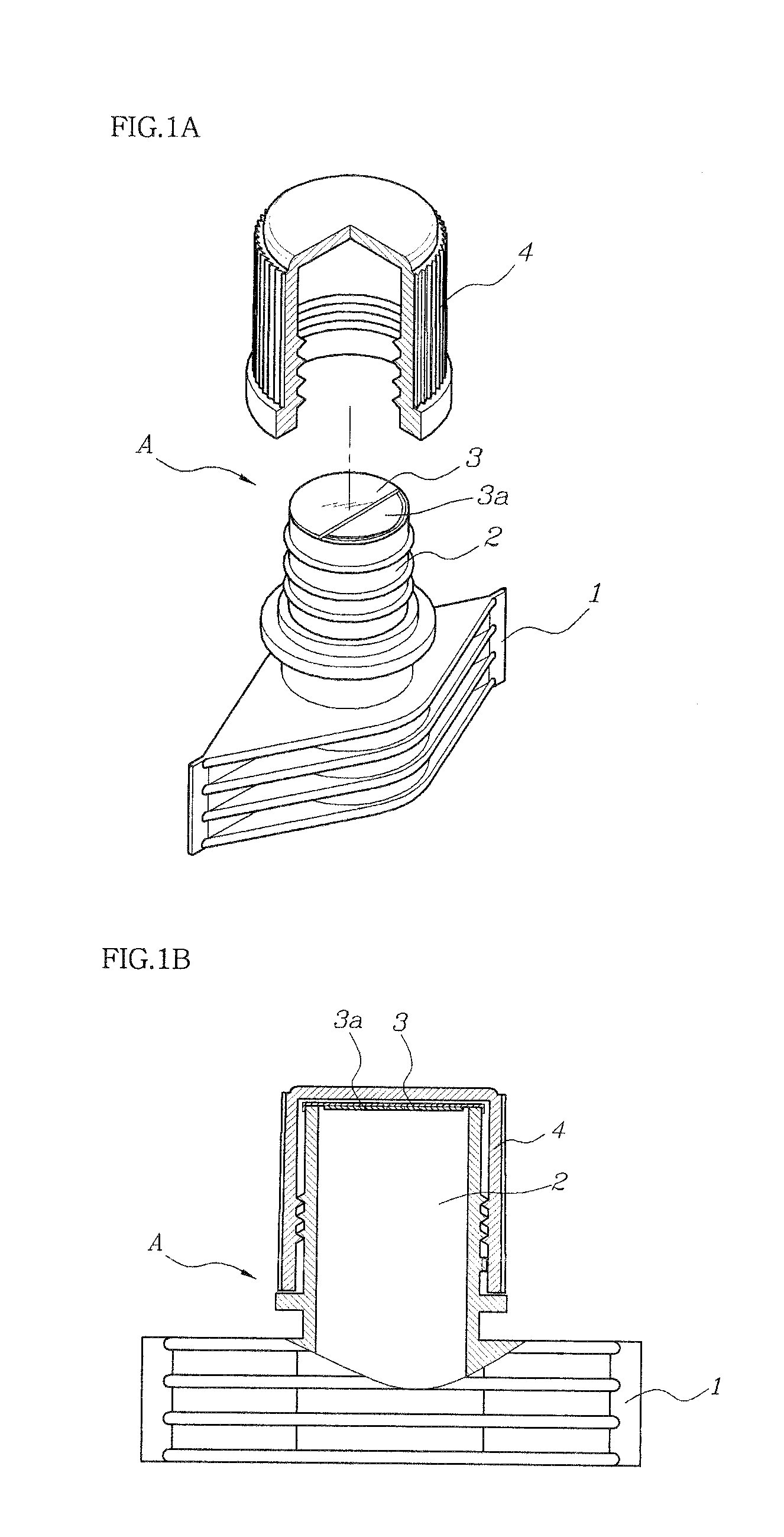
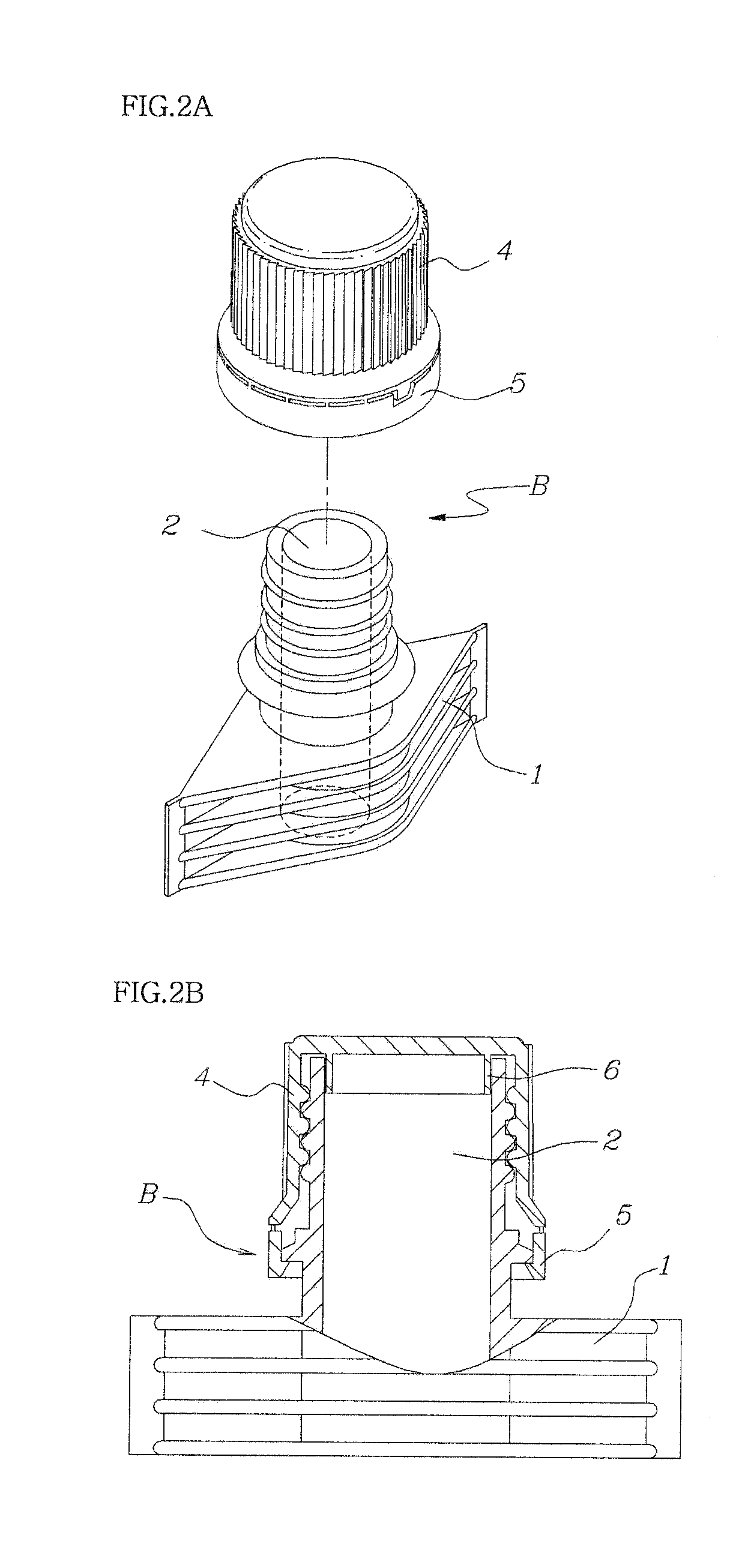
[0045]As illustrated in the drawings, the spout includes a body 10 which is bonded to a pouch 50, in which in general contents are filled, using e.g. a fusing method, and having an outlet 12 through which the contents are discharged from the pouch, a sealing end tube 30 which is integrally formed with the outlet via a thin and breakable sheet portion 32 so as to block the outlet, and a cap 20 which is spirally coupled with the body 10 so as to cover and protect the sealing end tube 30.

[0046]The cap 20 is made to be screw-coupled or spirally-coupled with the body 10, so that the cap and th...


PUM

PropertyMeasurementUnit
circumferenceaaaaaaaaaa
temperatureaaaaaaaaaa
stabilityaaaaaaaaaa

Abstract

A spout for a pouch includes a body integrally and fixedly connected with the pouch via a joint and having an outlet through which contents are discharged, a sealing end tube integrally formed with the outlet via a thin and breakable sheet portion so as to block the outlet, a cap spirally coupled with the body so as to cover and protect the sealing end tube, and a breaking means for opening the sealing end tube only upon opening of the cap such that the breakable portion is forcedly broken from the outlet.

Description

BACKGROUND OF THE INVENTION[0001]1. Field of the Invention[0002]The present invention relates, in general, to a spout for a pouch in which a cap is spirally combined with a body and, more particularly, to a spout for a pouch in which a sealing end tube, which is integrally formed with a body for blocking an outlet of the body, is safely protected by the cap when a product is distributed and is naturally removed from the outlet when the cap is manipulated and opened.[0003]2. Description of the Related Art[0004]As is well known in the art, a spout is generally used on a pouch in order to safely seal and discharge contents contained in the pouch. Such a spout includes a body having an outlet and a joint, which is fused onto the pouch, and a cap which is combined with the body in a screw-coupled manner or a one-touch manner in order to close the outlet. Further, according to the use (high or low temperature sterilization), an aluminum sheet may be attached to or a rib-like sealing porti...

Claims


Application Information

Patent Timeline
Patent Type & Authority Applications(United States)
IPC IPC(8): B65D25/40B65D41/34
CPCB65D2575/583B65D75/5883
Inventor KIM, SANG SOON
Owner KIM SANG SOON
Why Eureka
Try Eureka