
Apparatus for generating plasma

a plasma generating apparatus and plasma technology, applied in the direction of electric discharge tubes, electric lighting sources, electric discharge lamps, etc., can solve the problems of non-uniform electric field formation of plasma generating apparatuses within vacuum chambers, difficult to variously control the distribution of plasma within vacuum chambers

Inactive Publication Date: 2011-06-09
JEHARA CORP
View PDF4 Cites 129 Cited by
  • Summary
  • Abstract
  • Description
  • Claims
  • Application Information

AI Technical Summary

Benefits of technology

[0028]The apparatus may further include: a first gas controller configured to control an amount of gas introduced into the center gas shower head, and a second gas controller configured to control an amount of gas introduced into the edge gas shower head.
[0029]The apparatus may further include an RF power supply part configured to supply the RF power to the upper electrode and the edge inductive coil, wherein the RF power supply part may include: an RF source configured to generate an RF power

Problems solved by technology

However, because the plasma generating apparatus 10 uses only the inductive coil 13 as a means for forming an electric field within the vacuum chamber 11, the plasma generating apparatus 10 tends to non-uniformly form the electric field within the vacuum chamber 11.
Also, because the plasma generating apparatus 10 cannot diversely vary the distribution of the electric field, it is difficult to variously control the distribution of plasma within the vacuum chamber 11.

Method used


Image

  • Apparatus for generating plasma
  • Apparatus for generating plasma
  • Apparatus for generating plasma

Examples


Embodiment Construction

[0062]The following detailed description is provided to assist the reader in gaining a comprehensive understanding of the methods, apparatuses, and / or systems described herein. Accordingly, various changes, modifications, and equivalents of the systems, apparatuses and / or methods described herein will be suggested to those of ordinary skill in the art. The progression of processing steps and / or operations described is an example; however, the sequence of steps and / or operations is not limited to that set forth herein and may be changed as is known in the art, with the exception of steps and / or operations necessarily occurring in a certain order. Also, descriptions of well-known functions and constructions may be omitted for increased clarity and conciseness.

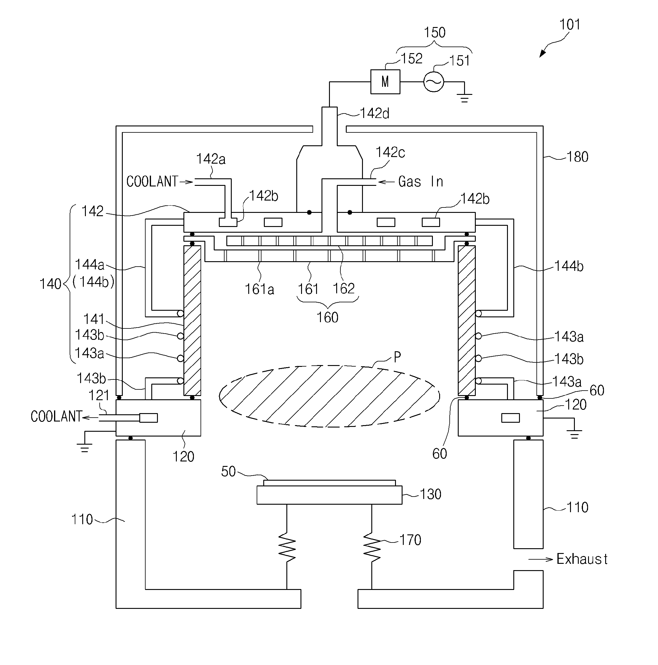
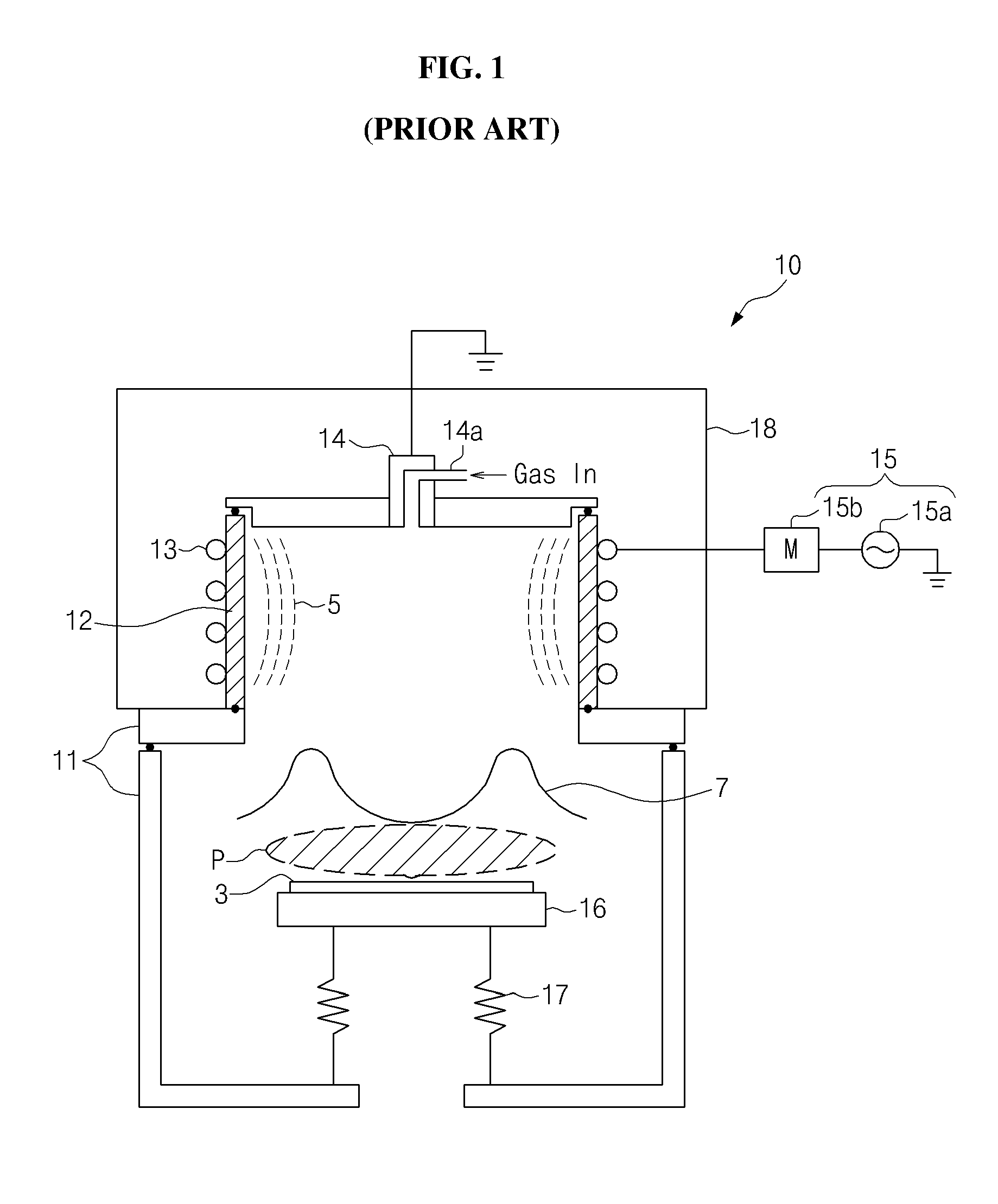
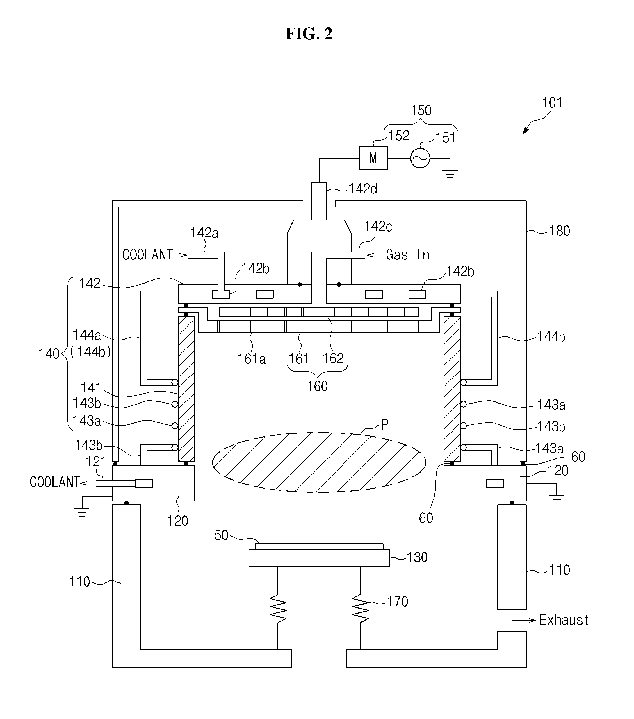
[0063]FIG. 2 is a schematic cross section of a plasma generating apparatus according to a first example embodiment. For the simplicity of drawings, FIG. 1 illustrates only key parts related to embodiments.

[0064]The plasma generat...


PUM

PropertyMeasurementUnit
Poweraaaaaaaaaa
Shapeaaaaaaaaaa
Electrical conductoraaaaaaaaaa

Abstract

An apparatus for generating plasma is provided. The apparatus may include a vacuum chamber and a plasma source part. The plasma source part may include a dielectric part, an upper electrode, and an inductive coil. The dielectric part may be installed to protrude upward along a circumference of a through-hole provided at a top of the vacuum chamber. The upper electrode may be coupled to seal an opened top of the dielectric part. The inductive coil may spirally extend along an outer circumference surface of the dielectric part.

Description

CROSS-REFERENCE TO RELATED APPLICATIONS[0001]This application claims the benefit under 35 U.S.C. §119(a) of Korean Patent Application No. 10-2009-0121501, filed on Dec. 9, 2009; and No. 10-2010-0059372, filed on Jun. 23, 2010; in the Korean Intellectual Property Office, the entire disclosure of each of which is incorporated herein by reference for all purposes.BACKGROUND[0002]1. Field[0003]The following description relates to an apparatus for generating plasma; more particularly, to an apparatus for generating plasma, including an upper electrode and an inductive coil.[0004]2. Description of the Related Art[0005]Generally, an apparatus for generating plasma is an apparatus for dissociating a reaction gas using an electromagnetic field, thereby generating free electrons, positive ions, neutral atoms, neutral molecules, etc.[0006]FIG. 1 is a schematic cross section of an apparatus for generating plasma according to the conventional art. As one example of the conventional art, FIG. 1 i...

Claims


Application Information

Patent Timeline
IPC IPC(8): H05B31/26
CPCH01J37/32091H01J37/321H01J37/32577H01J37/32174H01J37/3211
Inventor KIM, HONGSEUB
Owner JEHARA CORP
Features
  • Generate Ideas
  • Intellectual Property
  • Life Sciences
  • Materials
  • Tech Scout
  • Unparalleled Data Quality
  • Higher Quality Content
  • 60% Fewer Hallucinations
Learn More