
Offshore support structure and associated method of installing

a technology of support structure and support structure, which is applied in the direction of caissons, drilling pipes, artificial islands, etc., can solve the problems of increasing the complexity and weight of the transition piece located between the lower support and the wind turbine tower, increasing the material and installation cost, and increasing the cost of mono-piles as the base on which the wind turbine is placed

Active Publication Date: 2011-06-09
KEYSTONE ENG
View PDF16 Cites 31 Cited by
  • Summary
  • Abstract
  • Description
  • Claims
  • Application Information

AI Technical Summary

Problems solved by technology

Various conventional arrangements provide sufficient structurally support for the deck and offshore device but the associated dimensions of structures result in high material and installation expense.
However, with the movement of wind turbines further offshore, the employment of mono-piles as the base on which wind turbines are placed has become less cost effective.
Jacket type foundations or support structures with driven pipe piles have been used to support offshore wind turbines in recent years as the offshore wind industry has considered deeper water sites not previously considered feasible for monopile or gravity type foundations based on the added cost.
As turbines grew in size to generate more power, the complexity and weight of the transition piece, located between the lower supports and the wind turbine tower, increased.
The fabrication and installation of heavy wall joints can be a significant cost component to the wind turbine foundation.

Method used


Image

  • Offshore support structure and associated method of installing
  • Offshore support structure and associated method of installing
  • Offshore support structure and associated method of installing

Examples


Embodiment Construction

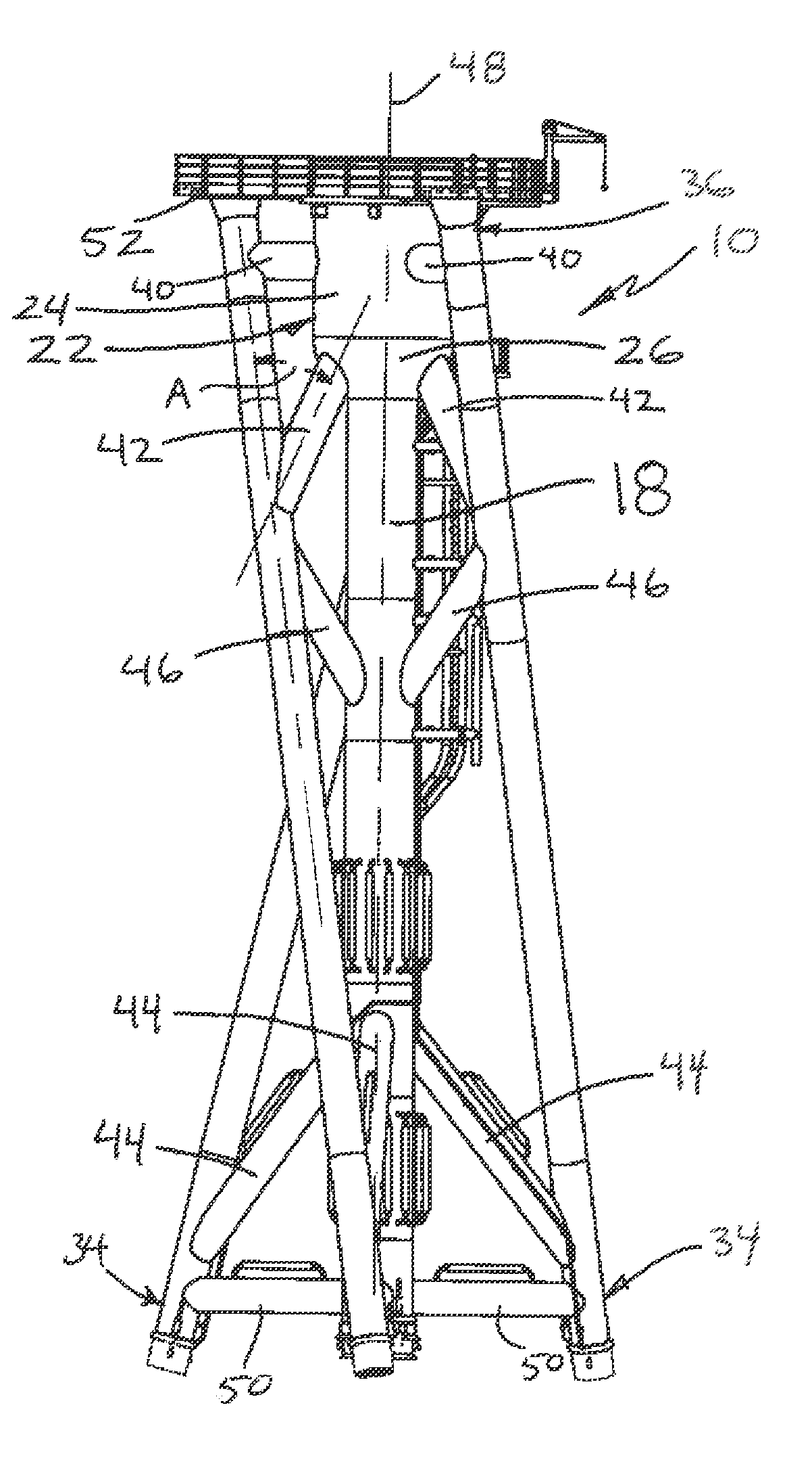
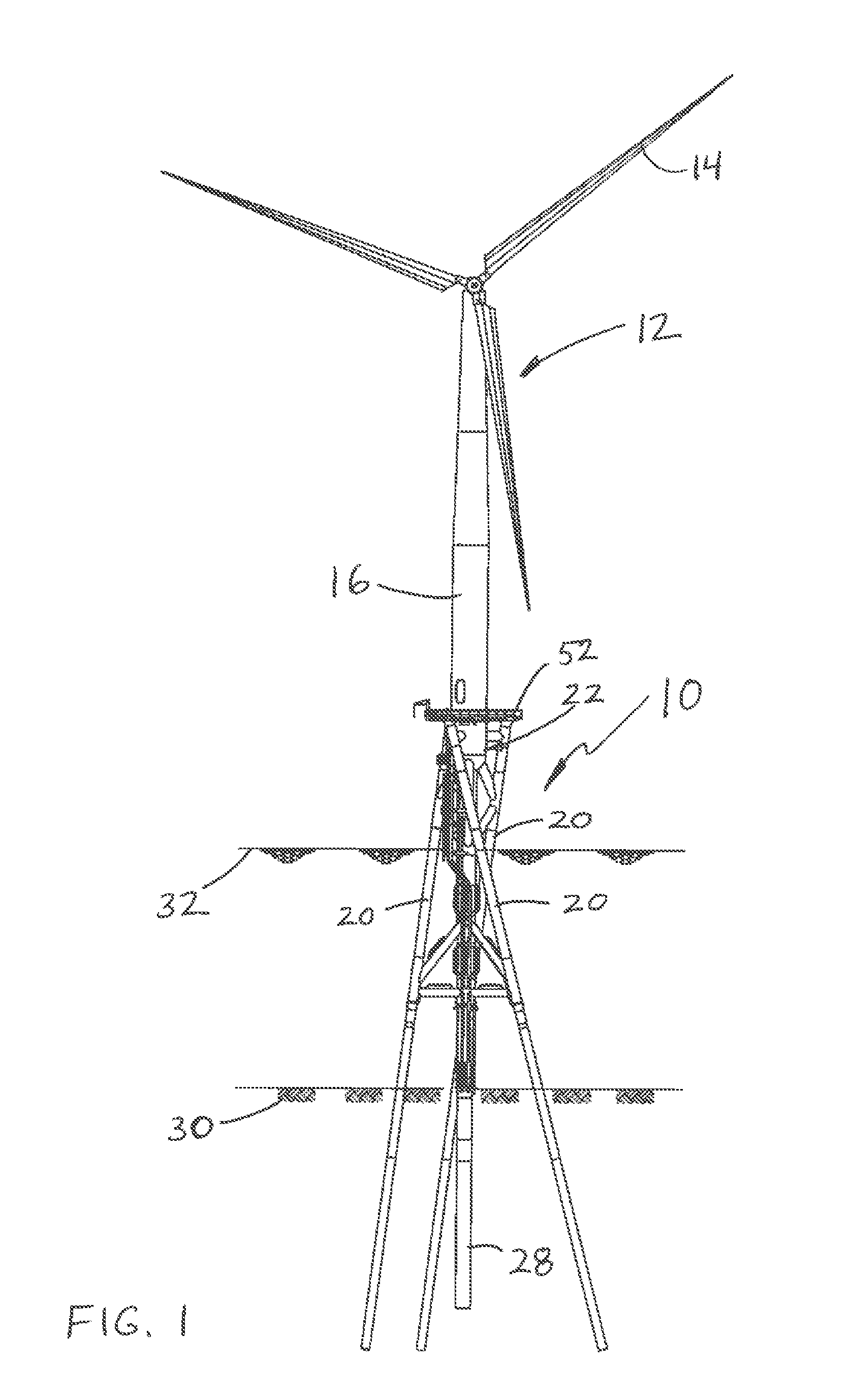
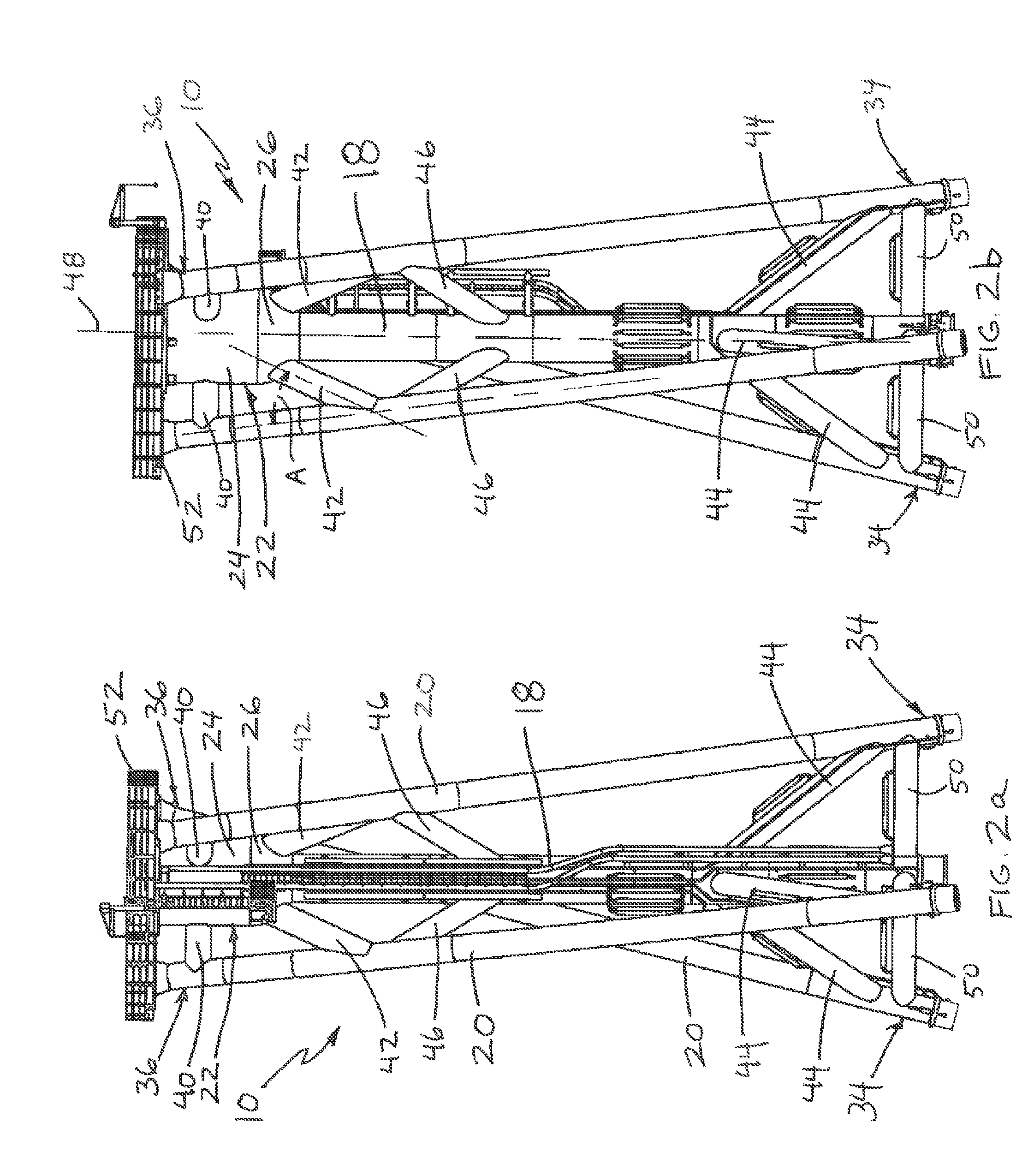
[0021]An exemplary embodiment of a support structure, and a method of assembling and installing the support structure, for supporting an offshore device, such as a wind turbine, including a transition joint having a convex portion, will be described in relation to an offshore wind turbine. Of course, the support structure may be used to support other offshore devices such as oil and / or gas drill platforms. To avoid unnecessarily obscuring the exemplary embodiments, the following description omits details of well known structures and devices that may be shown in block diagram form or otherwise summarized. For the purpose of explanation, other numerous specified details are set forth in order to provide a thorough understanding of the exemplary embodiments. It should be appreciated that the exemplary embodiments may be practiced in a variety of ways beyond these specified details. For example, the systems and methods of the exemplary embodiments can be generally expanded and applied t...


PUM


Abstract

A support structure for an offshore device and a method of assembling and installing the support structure, is provided including a vertical guide sleeve having, three elongated guide sleeves positioned around the vertical guide sleeve, and various braces connecting the elongated sleeves and the vertical guide sleeve. The support structure also includes a transition joint including a cylindrical portion for connection to an offshore device, such as a support tower of a wind turbine assembly, and a convex portion connected to the vertical guide sleeve. The transition joint may include a strengthening material in contact with an inner surface. The vertical sleeve, elongated sleeves, braces, and transition joint can be assembled onshore with lower piles installed in the elongated sleeves, this guide portion of the structure transported to the offshore location, and then piles driven to secure the structure to the floor of a body of water. The support structure minimizes the costs and time associated with material, assembly, and installation, while possessing sufficient strength, and effectively and efficiently handling and transferring loads from the wind turbine to the support surface throughout operation and while maintaining excellent fatigue resisting characteristics to withstand the extensive cyclic loading induced by the wind and waves.

Description

BACKGROUND[0001]1. Technical Field[0002]This invention generally relates to structures used to support offshore components. In particular, this invention relates to support structures for, for example, offshore wind turbines, or the like.[0003]2. Description of the Related Art[0004]Conventional offshore support structures have deck legs that are vertical or are battered outward as they extend downwards. Various conventional arrangements provide sufficient structurally support for the deck and offshore device but the associated dimensions of structures result in high material and installation expense. Wind turbines have traditionally been supported on mono-piles when placed offshore. However, recently, efforts include positioning wind turbines in deeper water (approximately six to seven or more miles offshore) in part to increase the aesthetics of the view from the shoreline. However, with the movement of wind turbines further offshore, the employment of mono-piles as the base on whi...

Claims


Application Information

Patent Timeline
IPC IPC(8): E02D29/00E02D29/09E02D11/00
CPCE02D27/52E02D27/42E02D27/425
Inventor HALL, RUDOLPH A.
Owner KEYSTONE ENG
Learn More