Lighting device with shaped remote phosphor

Active Publication Date: 2011-06-16
IDEAL IND LIGHTING LLC
View PDF26 Cites 50 Cited by
  • Summary
  • Abstract
  • Description
  • Claims
  • Application Information

AI Technical Summary

Benefits of technology

[0011]The present invention is directed to lamps and luminaires that have remote phosphors positioned in relation to the lamp light sources so heat spreading from the light sources to the remote phosphors is reduced or eliminated.

Problems solved by technology

While the reflective cup 13 may direct light in an upward direction, optical losses may occur when the light is reflected (i.e. some light may be absorbed by the reflector cup due to the less than 100% reflectivity of practical reflector surfaces).
In addition, heat retention may be an issue for a package such as the package 10 shown in FIG. 1, since it may be diffic

Method used


Image

  • Lighting device with shaped remote phosphor
  • Lighting device with shaped remote phosphor
  • Lighting device with shaped remote phosphor

Examples


Embodiment Construction

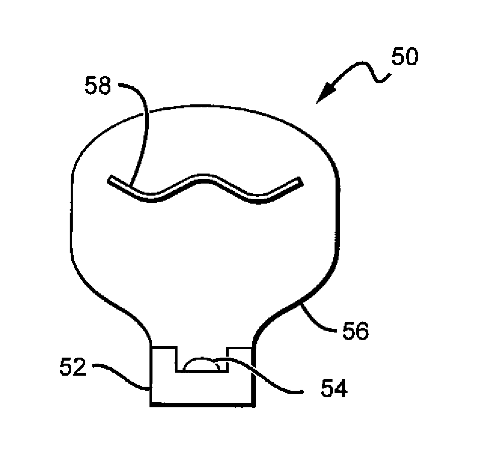
[0029]The present invention is directed to the use of shaped remote phosphors to provide more efficient and more uniform color and flux distribution of light from a lamp. The remote phosphors according to the present invention can be arranged to allow for operation of the lamp with minimal or no heat from the light source spreading into the phosphor. The remote phosphor is also arranged to minimize the amount of phosphor re-emitted light the passes through the phosphor material additional times following initial conversion. This reduces the amount of light that is absorbed by the remote phosphor and increases the overall emission efficiency of the lamp.

[0030]Embodiments according to the present invention can comprise one or more light emitting diodes (LED or LEDs) whose emission is incident on the remote phosphor so that at least some of the light is absorbed by the phosphor and re-emitted at a different wavelength of light. In one embodiment, the LEDs can emit a blue light, with th...


PUM


Abstract

Solid state lighting (SSL) luminaires are disclosed having remote phosphors arranged to minimize heat degradation and to efficiently convert light. One embodiment of an SSL luminaire comprises a light emitting diode (LED) mounted in a base. An enclosure is mounted in relation to the base so that light from the LED emits into the enclosure. A remote phosphor is mounted in the enclosure with at least some light from the LED passing into the remote phosphor where at least some of the light is absorbed and re-emitted at a different wavelength and passing through the enclosure. The remote phosphor is mounted a sufficient distance from the LED so substantially no heat from the LED passes into said conversion material, and wherein the remote phosphor has an open compound shape.

Description

BACKGROUND OF THE INVENTION[0001]1. Field of the Invention[0002]This invention relates to lighting devices and in particular to solid state lighting devices comprising one or more light emitting diodes and remote conversion materials.[0003]2. Description of the Related Art[0004]Light emitting diodes (LED or LEDs) are solid state devices that convert electric energy to light, and generally comprise one or more active layers of semiconductor material sandwiched between oppositely doped layers. When a bias is applied across the doped layers, holes and electrons are injected into the active layer where they recombine to generate light. Light is emitted from the active layer and from all surfaces of the LED.[0005]In order to use an LED chip in a circuit or other like arrangement, it is known to enclose an LED chip in a package to provide environmental and / or mechanical protection, color selection, light focusing and the like. An LED package can also include electrical leads, contacts or ...

Claims


Application Information

Patent Timeline
IPC IPC(8): H01J1/62F21V9/40
CPCF21K9/56F21Y2101/02H01L2224/32245H01L2224/48091H01L2224/48247H01L2224/73265H01L2924/00014H01L2924/00H01L2924/181F21K9/64F21Y2115/10H01L2924/00012
Inventor NEGLEY, GERALD H.VAN DE VEN, ANTONY PAUL
Owner IDEAL IND LIGHTING LLC
Why Eureka
Try Eureka