Dimming bridge module

a technology of bridge module and dimming bridge, which is applied in the direction of electric variable regulation, process and machine control, instruments, etc., can solve the problems of material breakdown and/or failure, limiting the location of components coupled thereto, and requiring significant expense for hardwire control system installation and maintenance within the lighting system

Active Publication Date: 2011-06-16
GE LIGHTING SOLUTIONS LLC
View PDF11 Cites 112 Cited by
  • Summary
  • Abstract
  • Description
  • Claims
  • Application Information

AI Technical Summary

Benefits of technology

[0007]According to an aspect, a lighting control system is coupled to one or more ballast / drivers operating one or more light sources. A low power control module receives analog, digital and / or DALI signals from one or more sources, processes the signals to provide an appropriate lighting response and outputs one or more commands related to light output of the one or more ballast / drivers operating one or more light sources. A gateway component receives wireless signals from the low power control module to relay to one or more control components. The control components provide instruction to modify the light output of the one or more ballast / drivers operating one or more light sources based at least in part upon the one or more commands received from the low power control module and / or the gateway component.
[0008]According to another aspect, a lighting control system includes one or more zones, each zone is related to a predetermined area and includes a plurality of ballast / drivers, light sources and one or more sensors. A low power control module is associated with each of the one or more zones, each low power control module receive signals from the one or more sensors related to the associated zone, processes the signals to provide an appropriate lighting response for the associated zone and outputs one or more commands related to light output of the one or more light sources within the associated zone. One or more ballast / drivers, associated with each of the light sources within one or more zones, deliver power to the plurality of light sources based at least in part upon the one or more commands received from the low power control module.

Problems solved by technology

Hardwire control systems can require significant expense related to installation and maintenance within a lighting system.
Moreover, use of a physical connection to communicate with each ballast / driver and / or light source brings inherent problems associated with material breakdown and / or failure.
These high voltage lines often require housing in a conduit and / or other safety measures, which can limit the location of components coupled thereto.
Accordingly, increased costs can be incurred for additional materials, rerouting power and / or control lines, redesign of layout, etc.

Method used


Image

  • Dimming bridge module
  • Dimming bridge module
  • Dimming bridge module

Examples


Embodiment Construction

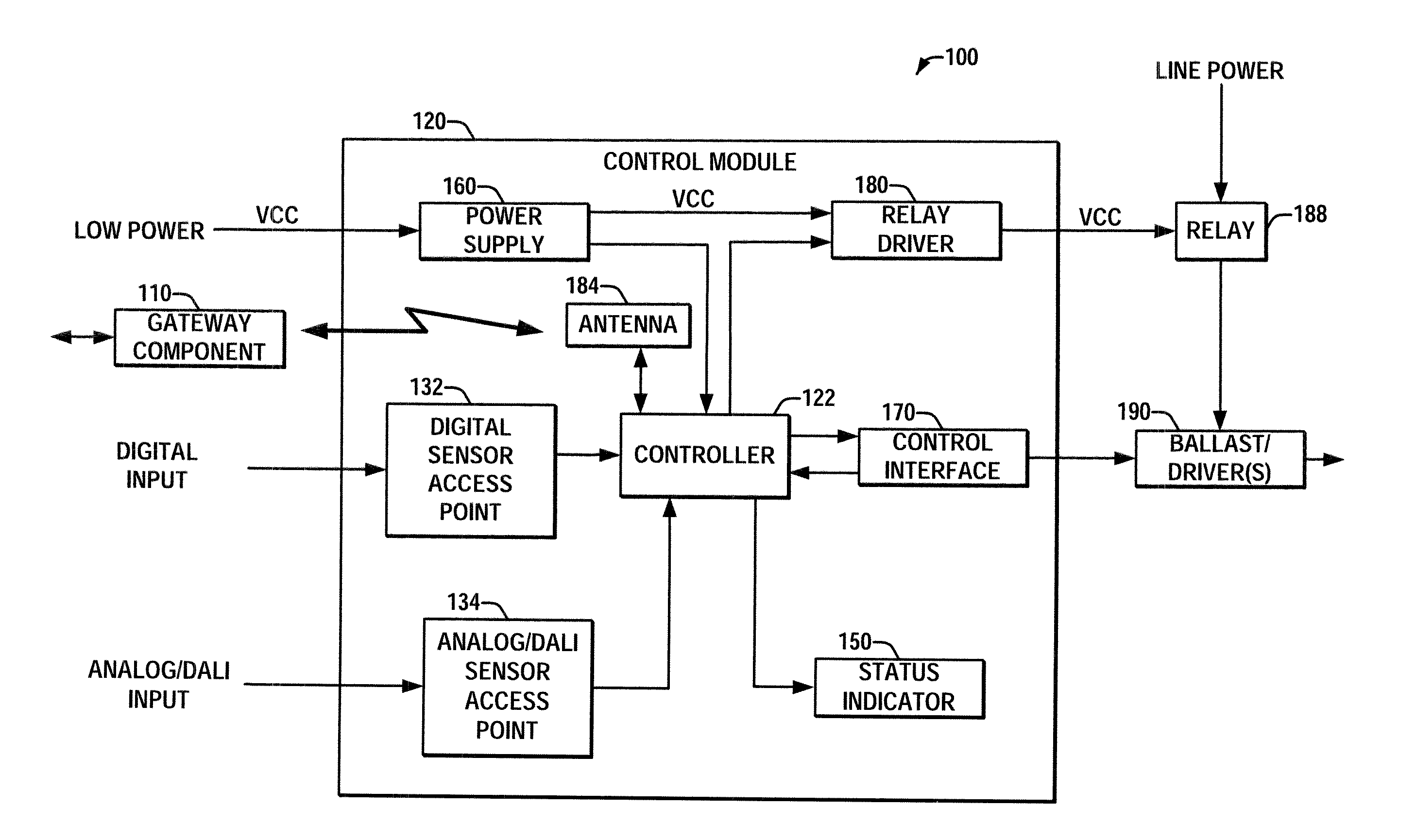
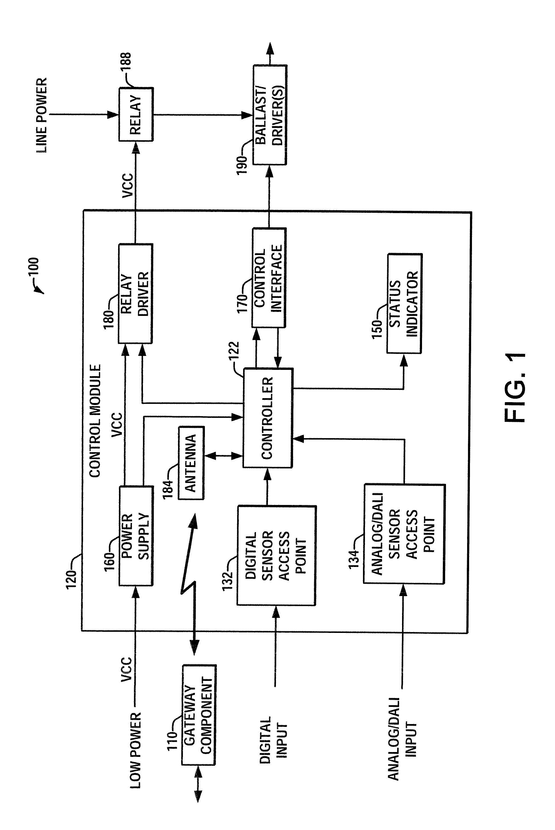
[0015]FIG. 1 illustrates a lighting control system 100 that includes a gateway component 110, a low power control module 120 and a ballast / driver(s) 190. The system 100 can be a mesh network wherein connections are dynamically updated and optimized to ensure operability and communication with the system 100 in substantially any condition. The low power control module 120 can receive digital, analog and / or DALI signals from one or more sources within the system 100 and provide local control to light sources and / or broadcast this information to one or more upstream control components to affect system-wide control. The signals received by the gateway component 110 can be sent from sensors, controllers, timers or other devices that impact light output within the control system 100. Alternatively or in addition, the signals from these devices can be received indirectly via one or more disparate gateway components. In this manner, signals transmitted from any device within a control syste...


PUM


Abstract

A lighting control system is coupled to one or more ballast/drivers operating one or more light sources. A low power control module receives analog, digital and/or DALI signals from one or more sources, processes the signals to provide an appropriate lighting response and outputs one or more commands related to light output of the one or more ballast/drivers operating one or more light sources. A gateway component receives wireless signals from the low power control module to relay to one or more control components. The control components provide instruction to modify the light output of the one or more ballast/drivers operating one or more light sources based at least in part upon the one or more commands received from the low power control module and/or the gateway component.

Description

BACKGROUND[0001]The present application is directed to interface circuits for lighting systems. It finds particular application in conjunction with low power low power control modules that receive hardwire signals from sensors, which are relayed wirelessly to high level controllers within a system architecture to facilitate control within lighting systems, and will be described with particular reference thereto. It is to be appreciated, however, that the present exemplary embodiments are also amenable to other like applications.[0002]Lighting control systems are frequently used to provide illumination to industrial buildings, commercial structures and other large spaces. Conventional lighting control systems include a user interface, a controller, a power supply, light sources (e.g., incandescent, florescent, etc.) and cable to couple the light sources to the controller and the power supply. The user interface can be employed to allow a user to turn on, turn off and dim light source...

Claims


Application Information

Patent Timeline
Patent Type & Authority Applications(United States)
IPC IPC(8): H05B37/02
CPCH05B37/0272H05B47/19H05B47/195
Inventor ELEK, JOSEPH G.THOMAS, EDWARDABOUMRAD, TONY
Owner GE LIGHTING SOLUTIONS LLC
Why Eureka
Try Eureka