Step motor

Active Publication Date: 2011-06-30
LG INNOTEK CO LTD
View PDF6 Cites 2 Cited by
  • Summary
  • Abstract
  • Description
  • Claims
  • Application Information

AI Technical Summary

Benefits of technology

[0009]An embodiment of the present invention is directed to providing a step motor which has an improved assembly characteristic.
[0010]To achieve the object of the present invention, the present invention provides a step motor comprising; a rotor in which a lead screw is coupled with a magnet; a stator in which the rotor is rotatably inserted and which applies a magnetic field to the rotor; a thrust bearing which supports an end of the lead screw; a housing in w

Problems solved by technology

However, the conventional step motor has some problems in that it is difficult to fix the cap to the housing after the coil spring is dispo

Method used


Image

  • Step motor
  • Step motor
  • Step motor

Examples


Embodiment Construction

[0015]The advantages, features and aspects of the invention will become apparent from the following description of the embodiments with reference to the accompanying drawings, which is set forth hereinafter.

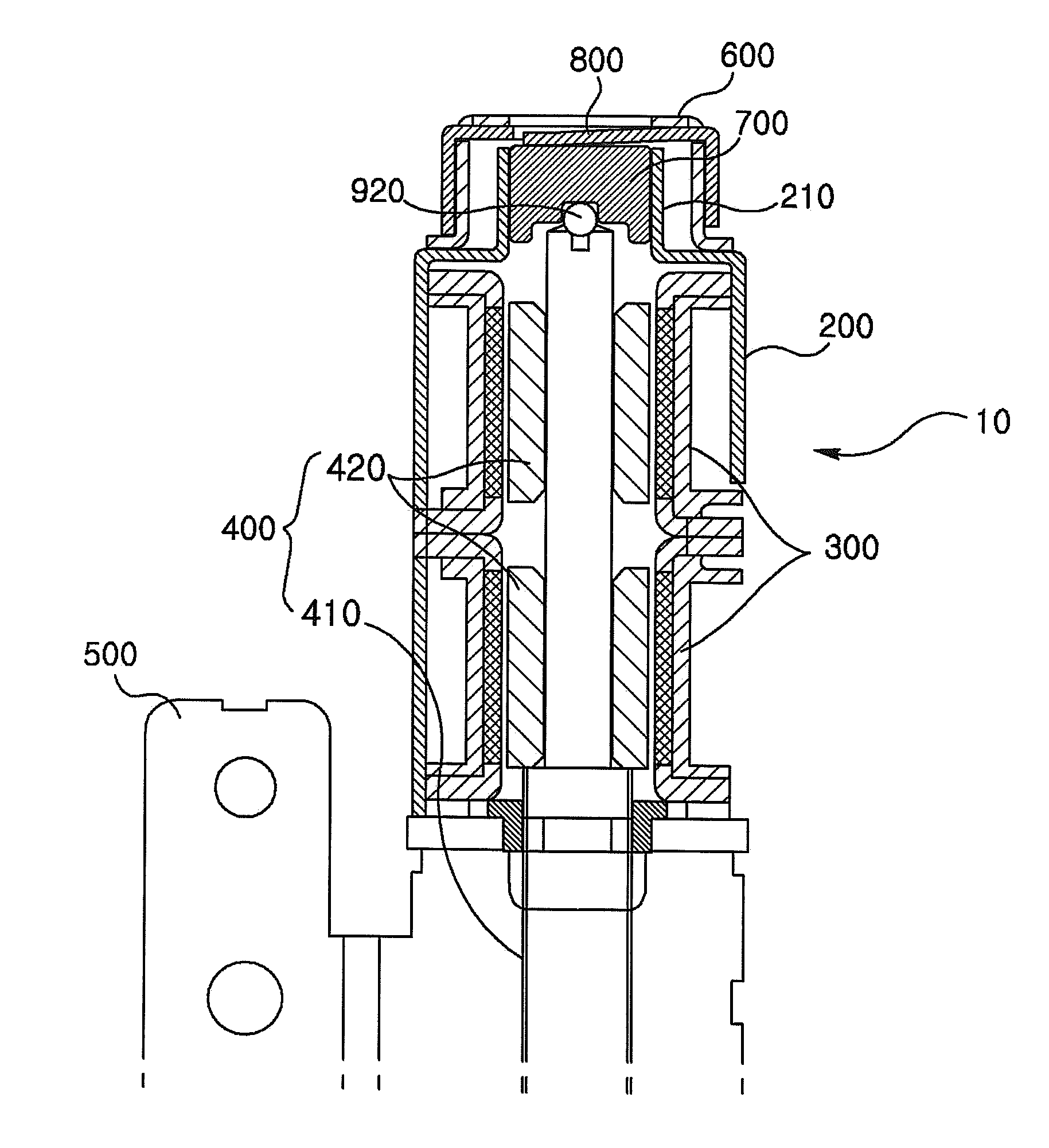
[0016]FIG. 1 is a cross-sectional view of a housing assembly structure of a step motor according to the present invention.

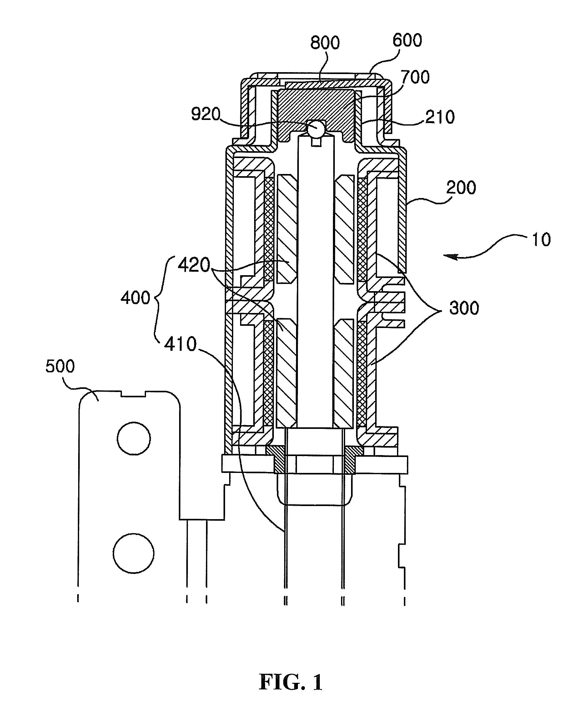
[0017]Referring to FIG. 1, a step motor of the present invention includes a housing 200, a stator 300, a rotor 400, a bracket 500, a plate spring guide 600, a thrust bearing 700 and a plate spring 800.

[0018]An opening part is formed at one side of the housing, and a guide part 210 is formed at the other side of the housing so as to guide a bearing device in an axial direction.

[0019]The stator 300 is disposed inside the housing 200 so as to form a magnetic field.

[0020]The rotor 400 includes a lead screw 410, and a magnet 420 which is fixed to a part of the lead screw 410. The magnet 420 is inserted into the stator 300 so as to have a desired gap, and the lead s...


PUM


Abstract

Provided is a step motor including a rotor in which a lead screw is coupled with a magnet; a stator in which the rotor is rotatably inserted and which applies a magnetic field to the rotor; a thrust bearing which supports an end of the lead screw; a housing in which the stator is received, and a guide part opened at one side thereof is protruded, and the thrust bearing is inserted into the guide part; a plate spring which is provided at an opened portion of the guide part so as to apply elastic force to the thrust bearing and thus inhibit deviation of the lead screw and the thrust bearing; and a plate spring guide which is fixed to an outside of the guide part of the housing so that the plate spring is inserted therein.

Description

CROSS-REFERENCE TO RELATED APPLICATION[0001]This application claims the benefit under 35 U.S.C. §119 of Korean Patent Application No. 10-2009-0135329, filed Dec. 31, 2009, which is hereby incorporated by reference in its entirety.BACKGROUND OF THE DISCLOSURE[0002]1. Field of the Invention[0003]The present invention relates to a step motor, and particularly, to a step motor in which a pressing structure of a thrust bearing supporting an axial end of a lead screw is improved.[0004]2. Discussion of the Related Art[0005]Generally, a step motor is widely used in various fields such as an optical apparatus, a printer and an automatically controlled machine tool. In the step motor, a transfer member is engaged with a lead screw so as to be transferred in an axial direction by driving of the motor.[0006]The step motor typically includes a rotor including a lead screw, a stator having a cylindrical shape in which the rotor is received in the stator, a housing which receives the rotor and the...

Claims


Application Information

Patent Timeline
IPC IPC(8): H02K5/16
CPCH02K5/161F16C17/08H02K37/00H02K37/02
Inventor YU, HYUNSOO
Owner LG INNOTEK CO LTD
Why Eureka
Try Eureka