Two piece console and seat assembly

a two-piece, console technology, applied in the direction of chairs, vehicle components, vehicle arrangements, etc., can solve the problems of affecting the assembly process, affecting the assembly quality, and affecting the installation technique of automated seats, so as to improve the assembly characteristics and improve the shipping profile

Inactive Publication Date: 2005-07-07
LEAR CORP
View PDF8 Cites 7 Cited by
  • Summary
  • Abstract
  • Description
  • Claims
  • Application Information

AI Technical Summary

Benefits of technology

[0005] It is therefore an object of the present invention to provide an automotive seat and console assembly with improved assembly characteristics. It is a further object of the present invention to provide an automotive seat and console assembly with improved shipping profile.

Problems solved by technology

It is precisely this vertical profile of current console assemblies that contributes to difficulties in manufacturing and assembly.
The pre-installed floor mounted consoles create a physical barrier that can interfere with automated seat installation techniques.
This may require specialized installation equipment or procedures and may even be unattainable due to space constraints.
Post seat console installation may be constrained by functional space constraints generated by the pre-installed seat assemblies.
Common center console designs as discussed, however, are commonly subject to vertical profile dimensions that introduce difficulties for pre-installation combination with seat assemblies.
This structural mount pole can interfere with standard center console profiles.
In addition, tooling utilized for installation of the seat assemblies also can interfere with the vertical profile of a standard console.

Method used


Image

  • Two piece console and seat assembly
  • Two piece console and seat assembly
  • Two piece console and seat assembly

Examples


Embodiment Construction

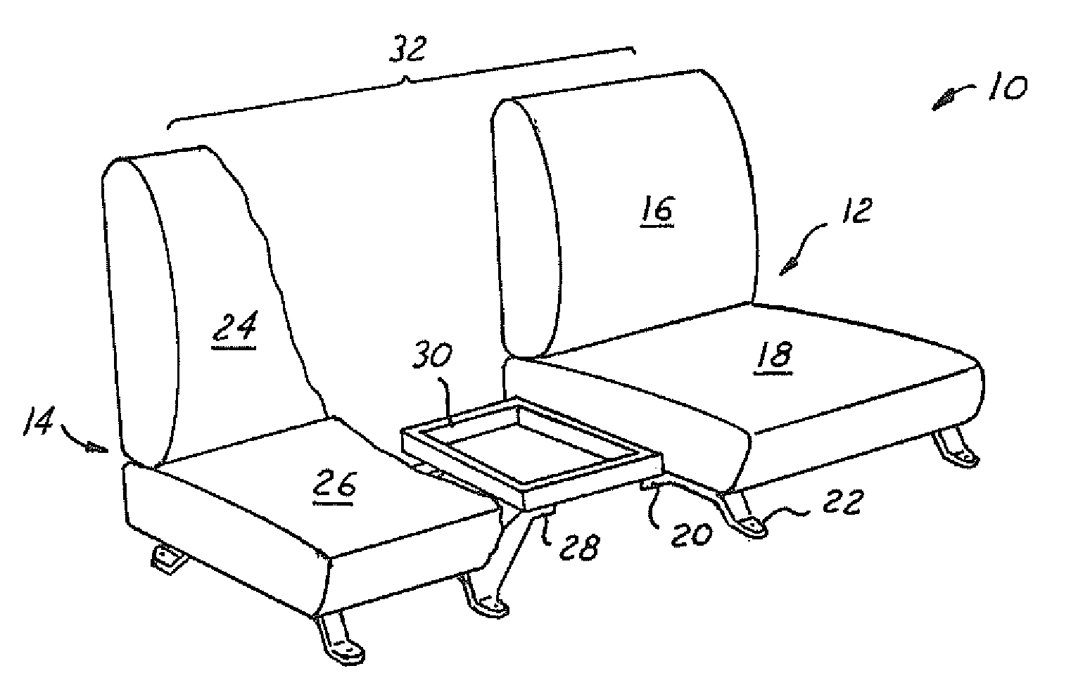
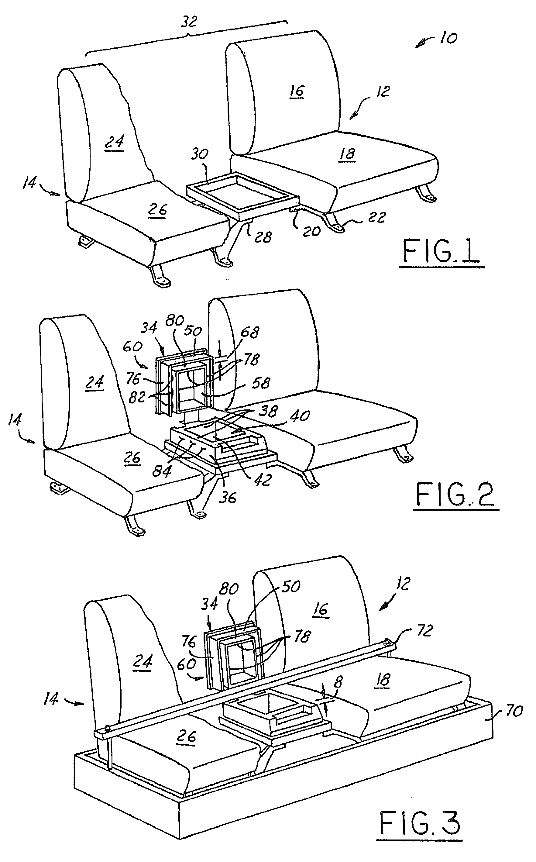
[0016] Referring now to FIG. 1, which is an illustration of an automotive seat assembly 10 in accordance with the present invention. It should be understood that the seat assembly 10 illustrated in FIG. 1 is intended to be illustrative of a wide variety of seating designs. The seat assembly 10 includes a first (driver side) seat 12 and a second (passenger side) seat 14. The driver side seat 12 is comprised of a driver seat back portion 16 and a driver seat base portion 18. A driver inboard mount assembly 20 protrudes inboard from the driver side seat 12. Although a variety of driver inboard mount assemblies are contemplated, one embodiment contemplates the driver inboard mount assembly 20 being formed as an extension of the driver seat mounts 22. Similarly, the passenger side seat 14 is comprised of a passenger seat back portion 24, a passenger seat base portion 26, and a passenger inboard mount assembly 28.

[0017] A joining frame 30 is mounted to the driver inboard mount assembly 2...


PUM


Abstract

An automotive seat assembly is provided including a driver side seat comprised of a driver seat back portion, a driver seat base portion, and a driver inboard mount assembly. The seat assembly further includes a passenger side seat comprised of a passenger seat back portion, a passenger seat base portion, and a passenger inboard mount assembly. A joining frame is mounted to the driver inboard mount assembly and the passenger inboard mount assembly to connect the driver side seat and the passenger side seat into a single installable seat component. A lower console base is mounted to the joining frame. The lower console base is comprised of a plurality of lower console base walls and an open lower console base top. The lower console base walls and the open lower console base top form a lower console base storage bin. An upper console base is comprised of a plurality of upper console base walls, an open upper console base top and an open upper console base bottom. The upper console base is rotatably attached to the lower console base such that the upper console base can be rotated between a pre-installation position and an installation position. The plurality of upper console base walls engage the plurality of lower console base walls to form an extended depth storage bin when the upper console base is in the installation position. A console lid is rotatably attached to the open upper console base top.

Description

BACKGROUND OF INVENTION [0001] The present invention relates generally to a automotive console assembly and more particularly to a two piece console and seat assembly with improved packaging and pre-installation profile. [0002] Automotive console assemblies play an important role in automobile design and functionality. Console assemblies are commonly positioned between individual seats to provide a wide variety of convenience features such as storage, a mounting surface for controls, and environmental controls and ports. Another common feature incorporated into these console assemblies is the ability to function as an armrest for one or more passengers within the vehicle. This requires the consoles, commonly mounted to the vehicle floor, to be designed with sufficient vertical height above the vehicle floor to properly function as arm rests. [0003] It is precisely this vertical profile of current console assemblies that contributes to difficulties in manufacturing and assembly. Floo...

Claims


Application Information

Patent Timeline
Patent Type & Authority Applications(United States)
IPC IPC(8): A47C7/62B60N2/01B60N2/015B60N3/10B60R7/04
CPCB60N2/01B60R7/04B60N3/101B60N2/015
Inventor MORABITO, RICHARDYATROS, JERRYCASS, MICHAEL W.GRESHAM, TIMOTHY S.
Owner LEAR CORP
Why Eureka
Try Eureka