Encapsulated pixels for display device

a technology of display device and encapsulation, which is applied in the manufacture of electrical instruments, instruments, electric digital data processing, etc., can solve the problems of deterioration of active optical elements such as liquid crystals, deterioration of visual displays, and deterioration of optical elements, so as to improve inductive coupling

Active Publication Date: 2011-06-30
POWERMAT TECHNOLOGIES
View PDF99 Cites 43 Cited by
  • Summary
  • Abstract
  • Description
  • Claims
  • Application Information

AI Technical Summary

Benefits of technology

[0016]The display may further include ferromagnetic material for improving inductive coupling between the primary inductive coil and the secondary inductor.

Problems solved by technology

Active optical elements such as liquid crystals, may deteriorate over time.
Exposure to dampness and air within the environment may hasten this deterioration, particularly where the optical elements are susceptible to oxidation.
Connecting wires crossing the protective layer introduce leaky channels through which air seepage may occur, thereby hastening the deterioration of the optical elements.
A further cause of deterioration of visual displays is the excitation voltage itself which can cause some optical elements, such as liquid crystals, to be degraded by electrolysis.
Much time and effort is devoted to finding cost effective solutions to overcome this problem.

Method used


Image

  • Encapsulated pixels for display device
  • Encapsulated pixels for display device
  • Encapsulated pixels for display device

Examples


Embodiment Construction

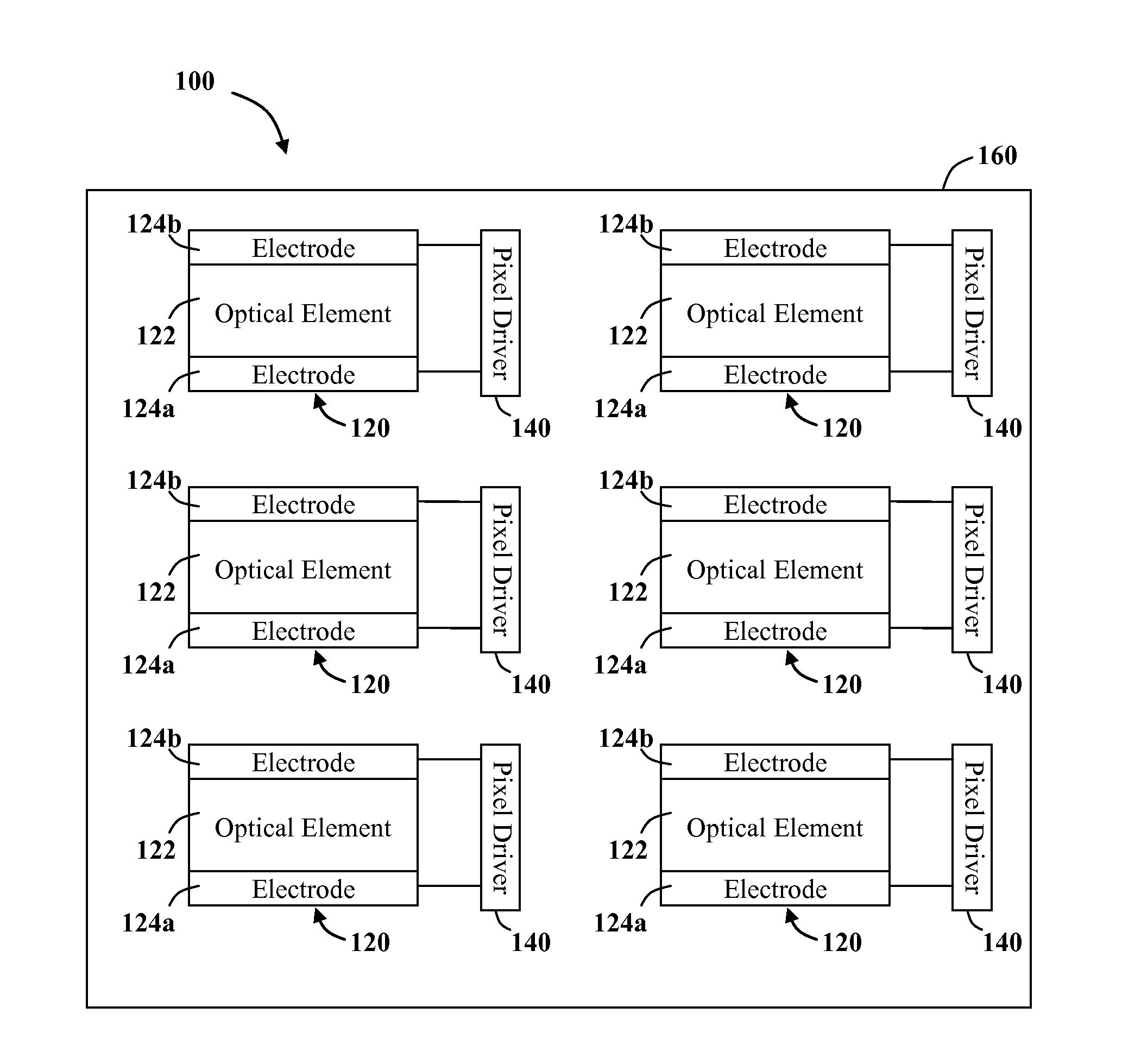
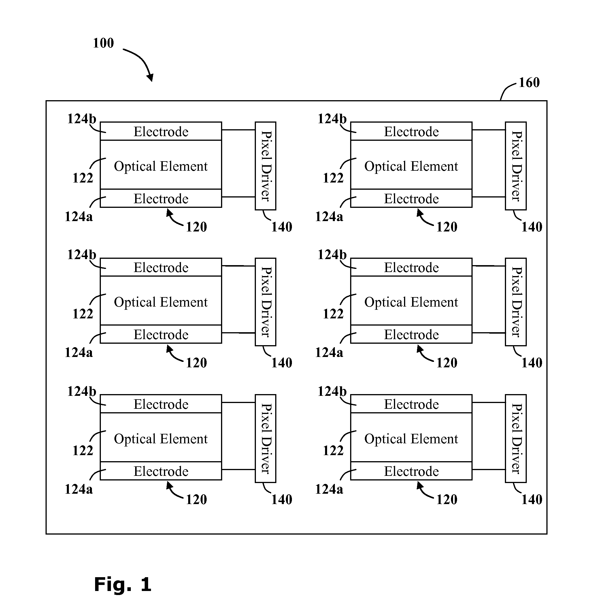
[0038]Reference is now made to FIG. 1 showing a block diagram representing the main components of an encapsulated display device 100 according to a first embodiment of the current invention. The display device 100 comprises a plurality of pixels 120.

[0039]Each pixel 120 includes an optical element 122 sandwiched between two electrodes 124a, 124b wired to a pixel driver 140. It is a particular feature of the current invention that the pixel 120 and pixel driver 140 are hermetically sealed from the environment by an encapsulating sealing layer 160 therearound.

[0040]The optical element 122 includes an optically active material, such as a liquid crystal, capable of assuming two or more physical states, the optical characteristics thereof, depending upon its state. The driver 140 is configured to provide a switching voltage across the electrodes 124 such that when the switching voltage exceeds a predetermined threshold, the optical state of the optical element changes from a first optica...


PUM

PropertyMeasurementUnit
resonant frequencyaaaaaaaaaa
oscillating frequencyaaaaaaaaaa
insulatingaaaaaaaaaa

Abstract

A display device comprising an array of encapsulated pixels. The encapsulating pixel includes an optical element which is altered from a first optical state to a second optical state upon when a potential difference is generated across it. The optical element is in contact with two electrodes which are connected to a pixel driver for generating the potential difference. The encapsulated pixel is hermetically sealed from the environment by a sealing layer and the driver receives power wirelessly via an inductive power transmission system.

Description

CROSS-REFERENCE TO RELATED APPLICATIONS[0001]This application is a continuation of International Application No. PCT / IL2009 / 000681 filed Jul. 8, 2009, which claims priority to U.S. Provisional Application 61 / 129,604 filed Jul. 8, 2008, the disclosures of which are hereby incorporated by reference in their entirety.FIELD OF THE INVENTION[0002]The present invention is directed to providing a visual display unit. More specifically, the invention is directed to providing a display device that is protected from the environment by encapsulation.BACKGROUND[0003]Visual display units (VDUs) are used to present information visually. Electronic VDUs include television sets and computer monitors for example. They receive information as electric signals and convert them for display as visual images on a screen.[0004]Electronic display units, such as liquid crystal displays (LCDs), for example, may consist of pixels, which are discrete optical elements. The optical states of these elements change...

Claims


Application Information

Patent Timeline
Patent Type & Authority Applications(United States)
IPC IPC(8): G09G5/00H05K13/00
CPCG02F1/1333G02F2001/133311G02F2201/50Y10T29/49007G02F1/1339G02F1/13452G02F1/1334G02F1/133311G02F1/13G02F3/02
Inventor BEN-SHALOM, AMIR
Owner POWERMAT TECHNOLOGIES
Why Eureka
Try Eureka