

Surveillance system with dual camera modules
a technology of surveillance system and camera module, applied in the field of surveillance system, can solve the problems of deteriorating video clarity, missing some activities, and both systems present limitations
- Summary
- Abstract
- Description
- Claims
- Application Information
AI Technical Summary
Benefits of technology
Problems solved by technology
Method used
Image

Examples
Embodiment Construction
Embodiments of the disclosure are now described in detail with reference to the drawings.
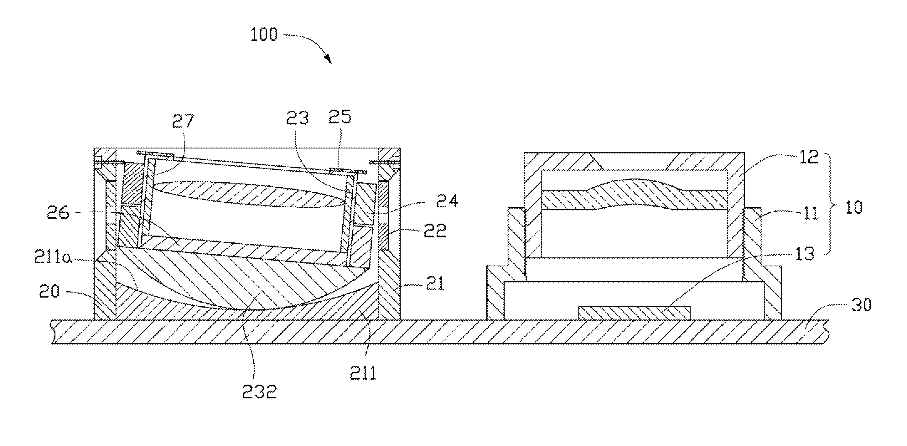
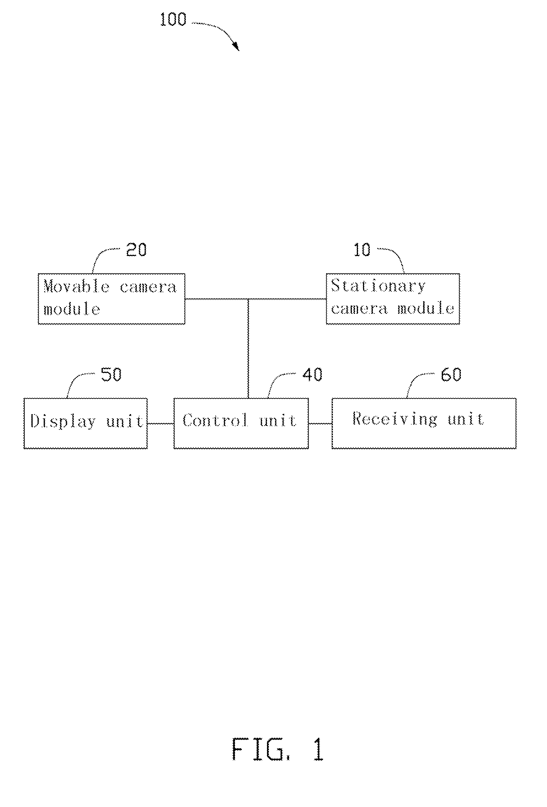
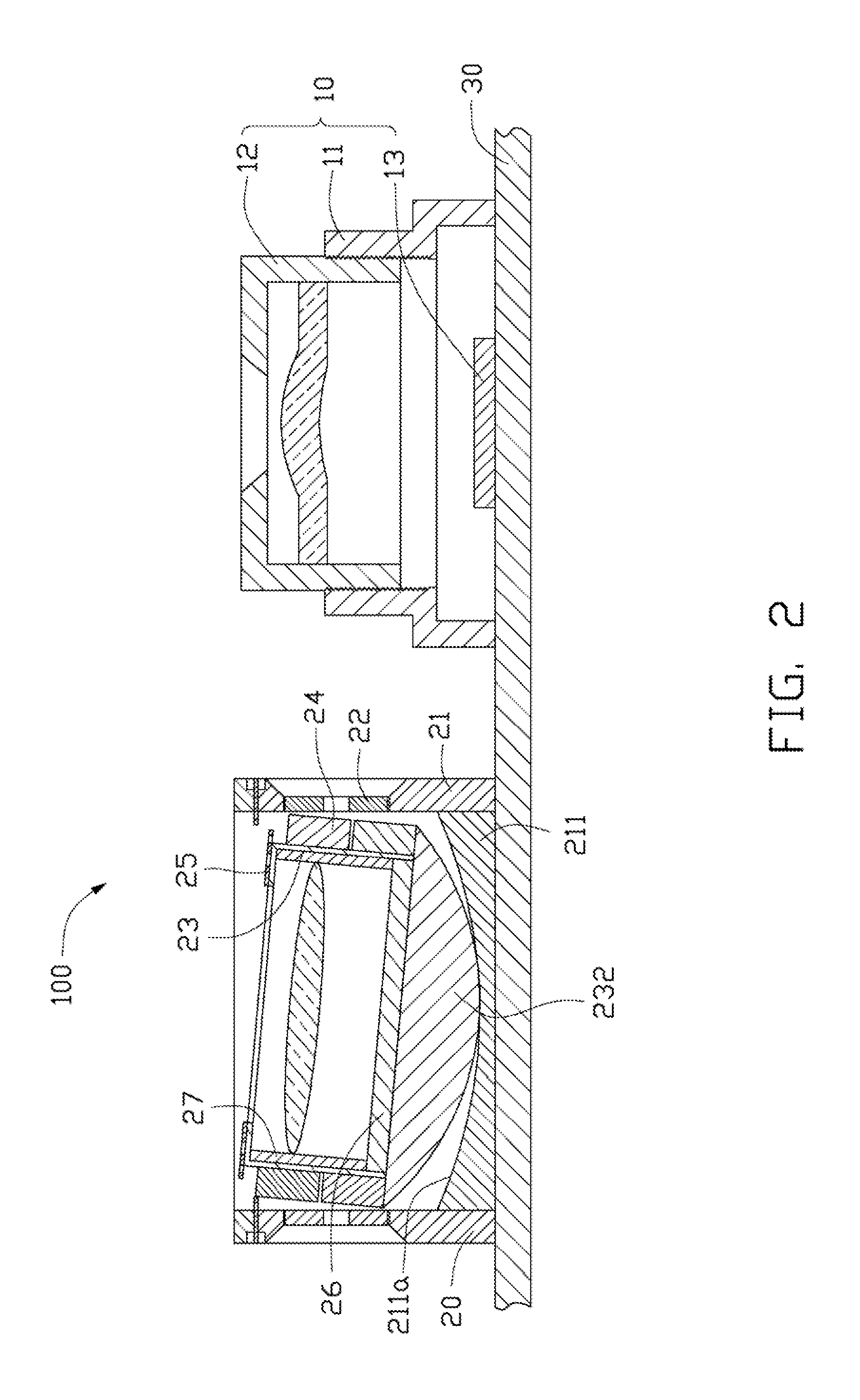
Referring to the FIGS. 1-2, a surveillance system 100, according to one exemplary embodiment, includes a stationary camera module 10, a movable camera module 20, a base plate 30, a control unit 40, a display unit 50, and a receiving unit 60.
The stationary camera module 10 includes a fixed focus lens, and is configured for capturing information from a total field of view of the surveillance system 100 to form global images. In particular, the stationary camera module 10 includes a lens holder 11, a first lens barrel 12, and a first image sensor 13. The first lens barrel 12 is partially received in the lens holder 11. The first image sensor 13 is disposed under the first lens barrel 12, received in the lens holder 11, and configured for converting light passing through the first lens barrel 12 to electric image signals. To monitor a wider area, the stationary camera module 10 is a wide-angle camer...
PUM
 Abstract
Description
Claims
Application Information