Stamping machine

a technology of stamping machine and displacement mechanism, which is applied in the direction of embossing decorations, printing, hand-made tools, etc., can solve the problem of cumbersome maintenance of the displacement mechanism

Active Publication Date: 2011-07-14
ROLAND DG CORP
View PDF12 Cites 20 Cited by
  • Summary
  • Abstract
  • Description
  • Claims
  • Application Information

AI Technical Summary

Problems solved by technology

In prior art engraving devices, dust or other foreign matters generated during the engraving process would tend to enter a displacement mechanism, thereby making the maintenance of the displacement mechanism cumbersome.

Method used


Image

  • Stamping machine
  • Stamping machine
  • Stamping machine

Examples


Embodiment Construction

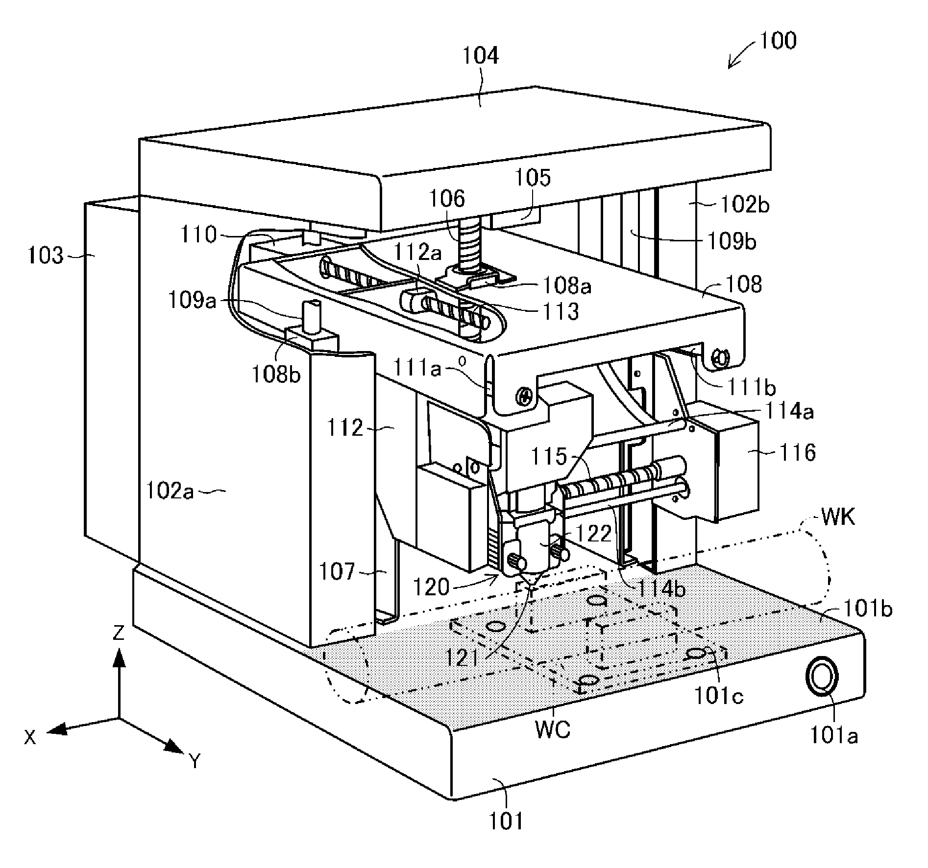
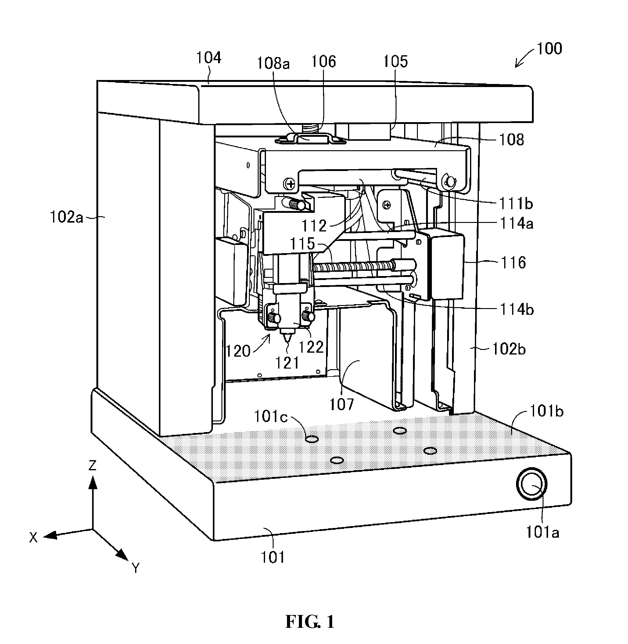
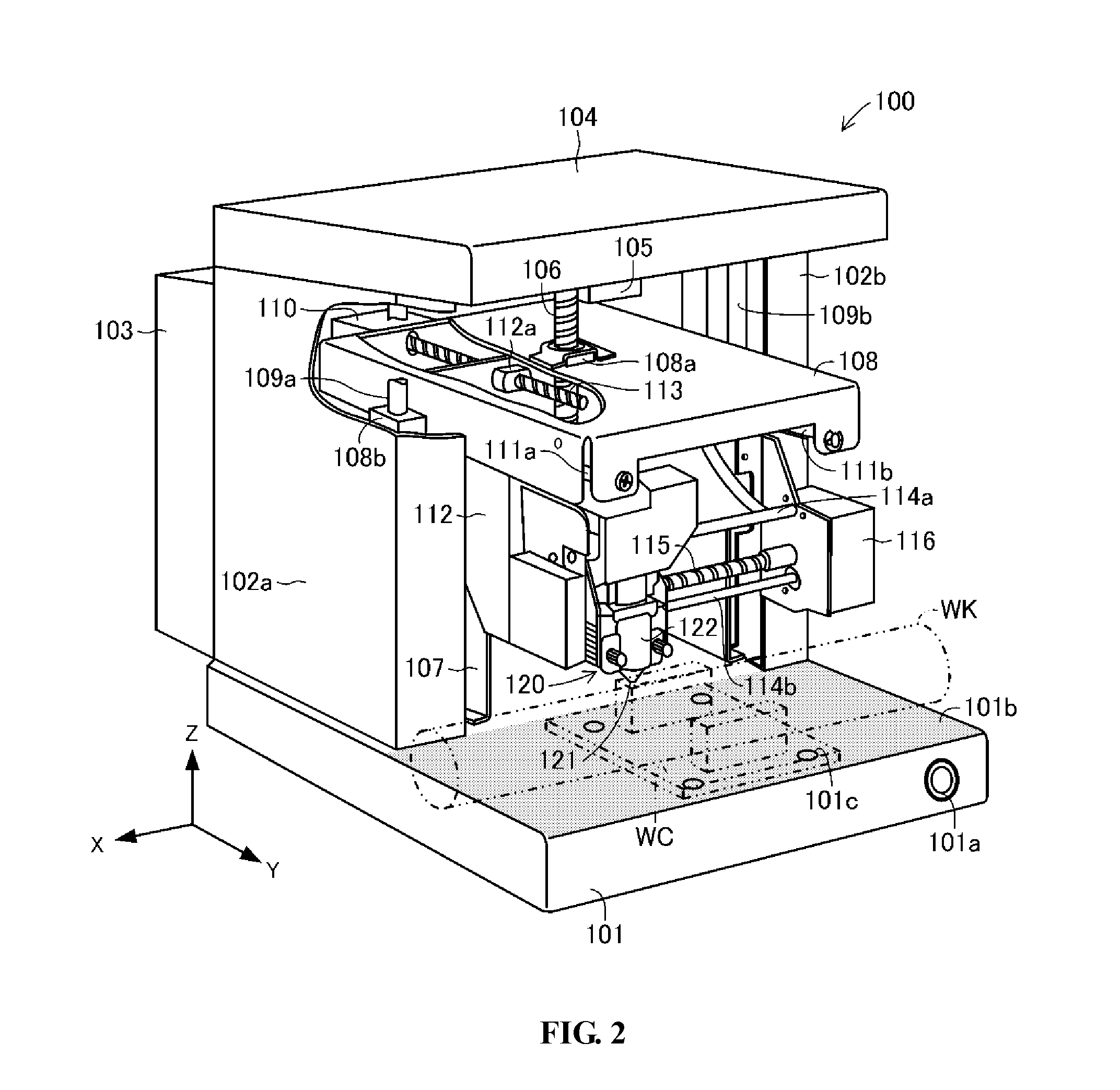
[0020]In the following detailed description, reference is made to the accompanying drawing figures which form a part hereof, and which show by way of illustration specific embodiments of the invention. It is to be understood by those of ordinary skill in this technological field that other embodiments may be utilized, and structural, electrical, as well as procedural changes may be made without departing from the scope of the present invention. Wherever possible, the same reference numbers will be used throughout the drawings to refer to the same or similar parts.

[0021]It should be noted that the drawings used herein are schematically depicted to facilitate understanding of the present invention, for example, some elements may be exaggerated. Thus, the dimensions and proportions between constituent elements may be different. In addition, the lateral direction of the drawing, the depth direction of the drawing, and the vertical direction of the drawing are defined as X-direction, Y-d...


PUM


Abstract

An engraving device that forms a desired image via a plurality of engraved marks in a surface of an object via a working tool is presented. The engraving device includes a base comprising a retainer configured to retain the object, a X-direction displacement means located above the base, configured to displace the working tool along a X-axis along the surface of the object, a Y-direction displacement means located above the base, configured to displace the working tool along a Y-axis perpendicular to the X-axis along the surface of the object, and a Z-direction displacement means located above the base, configured to displace the working tool along a Z-axis toward and away from the object.

Description

CROSS-REFERENCE TO RELATED APPLICATIONS[0001]Pursuant to 35 U.S.C. §119(a), this application claims the benefit of earlier filing date and right of priority to Japanese Patent Application No. 2010-005310, filed on Jan. 13, 2010, the contents of which is hereby incorporated by reference herein in its entirety.BACKGROUND OF THE INVENTION[0002]1. Field of the Invention[0003]The present invention relates to an engraving device that forms an image on a surface of an object.[0004]2. Discussion of the Related Art[0005]In general, an engraving device forms an image on the surface of an object by engraving a plurality of marks on a surface of an object composed of a relatively formable material such as gold, platinum, brass, aluminum, or stainless steel. For example, an engraving device may form a desired image on an object by driving a tip of an engraving rod into a surface of an object to form a plurality of dot engraved marks in the surface of the object.[0006]In prior art engraving devic...

Claims


Application Information

Patent Timeline
Patent Type & Authority Applications(United States)
IPC IPC(8): B44B11/02
CPCB44B3/063B44B3/009
Inventor KUNO, TSUTOMU
Owner ROLAND DG CORP
Why Eureka
Try Eureka