Self resetting target apparatus

Active Publication Date: 2011-07-21
CHALLENGE TARGETS
View PDF16 Cites 25 Cited by
  • Summary
  • Abstract
  • Description
  • Claims
  • Application Information

AI Technical Summary

Benefits of technology

[0011]It is another objective of the invention to provide an improved self-resetting and remotely-controllable reactive target.
[0012]To this end, one preferred embodiment of the invention contemplates a lightweight, portable, target that can be configured for multiple training exercises and recreational uses. The target can be used w

Problems solved by technology

The visual response with a spring resetting target is very quick and uneven.
Although the springs can be changed to achieve different reactions, changes to the speed and motion of the shot response are limited.
This motion does not create a realistic visual shot response.
As such, they drain the power source with each reset of the target or require manual exertion.
Most “automated” units require 3-8 seconds to r

Method used


Image

  • Self resetting target apparatus
  • Self resetting target apparatus
  • Self resetting target apparatus

Examples


Embodiment Construction

[0035]While the present invention is susceptible of embodiment in various forms, there is shown in the drawings and will hereinafter be described presently preferred embodiments with the understanding that the present disclosure is to be considered an exemplification of the invention and is not intended to limit the invention to the specific embodiment illustrated.

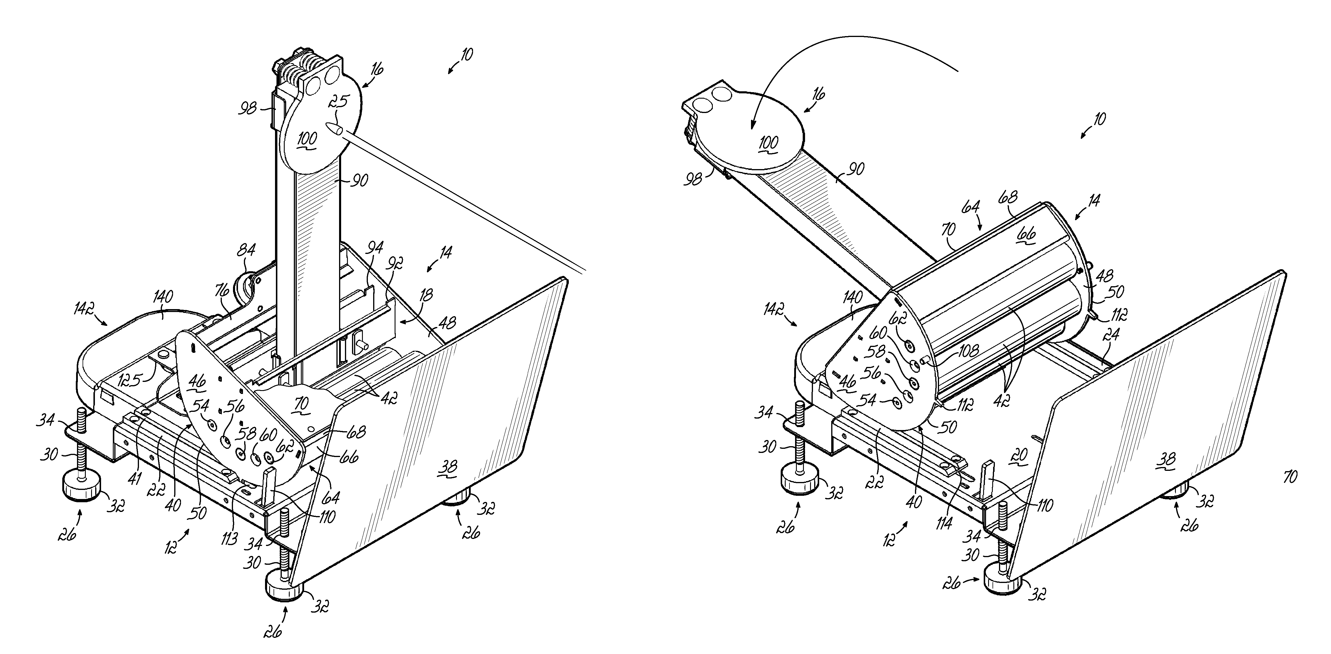
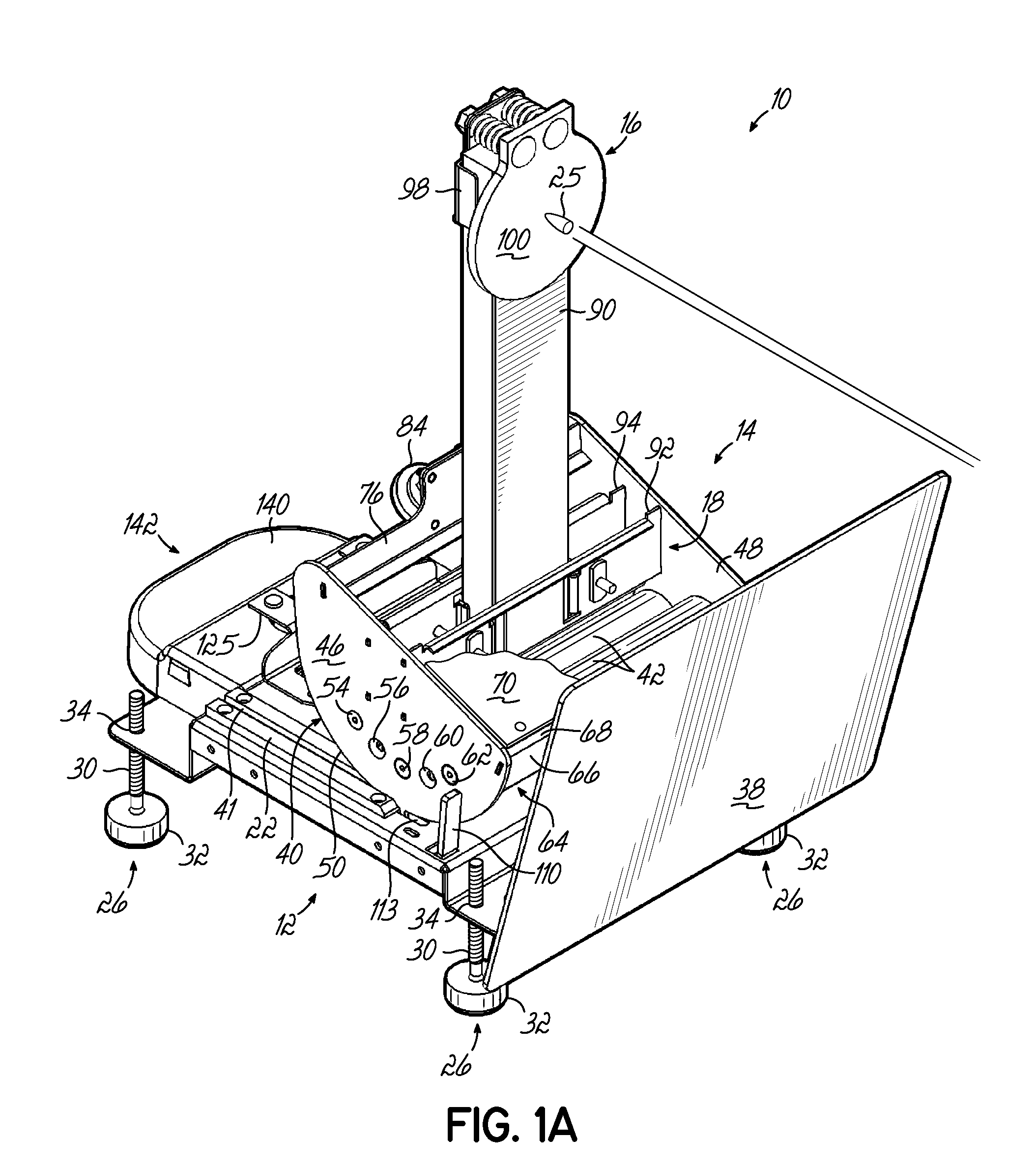
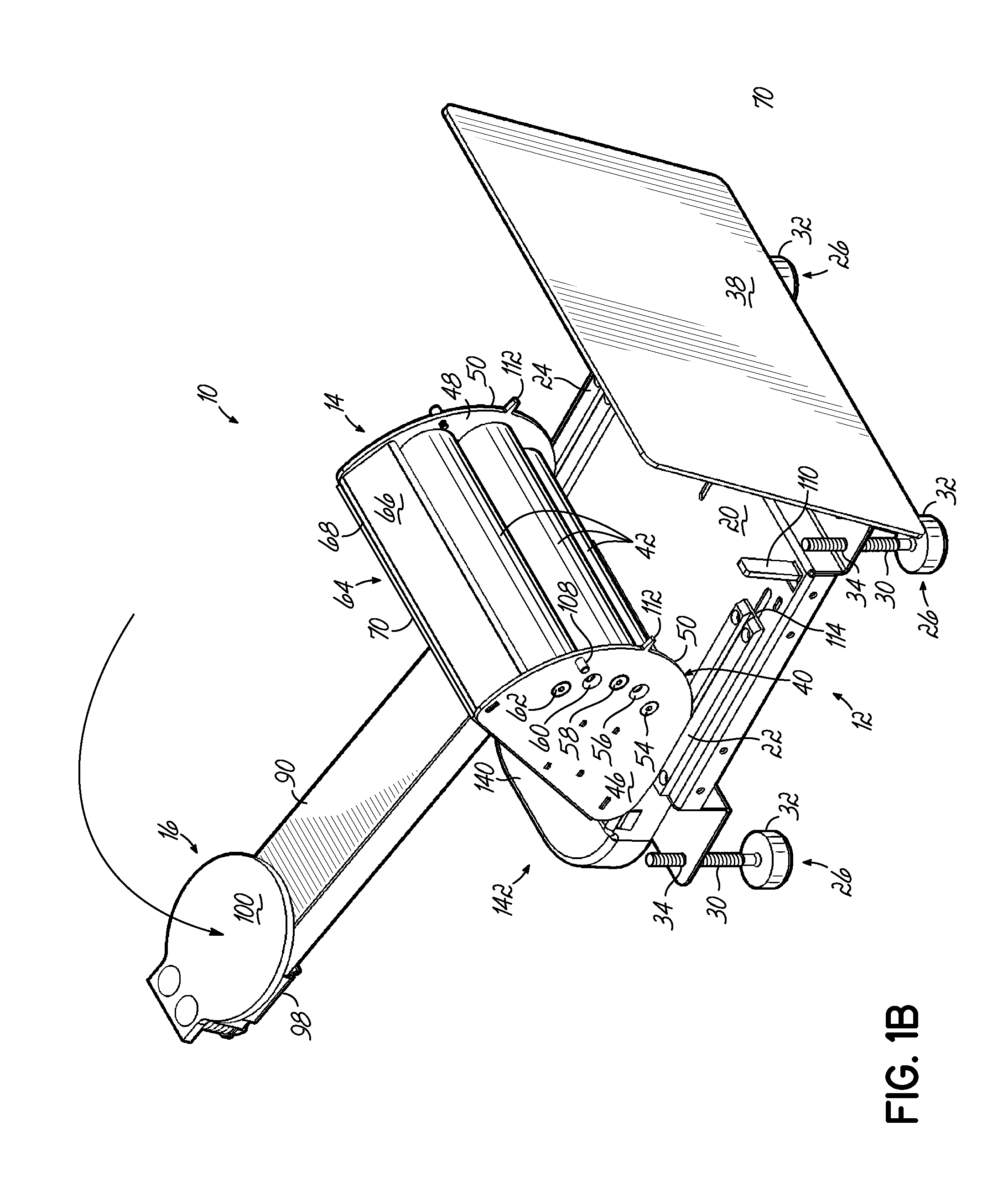
[0036]As shown generally in FIGS. 1-11C, the target apparatus 10 of the present invention has a base 12 and a rocker assembly 14. The basic elements of the base 12 and the rocker assembly 14 allow a target 16 that is coupled to target support 18 to move between an upright position (see FIGS. 1A and 1C) and a horizontal position (FIG. 1B). These basic elements, which are described in greater detail, may be variously configured to allow the target apparatus 10 to be employed in various settings for multiple uses.

[0037]The base 12, shown best in FIGS. 2-4, provides a flat surface for supporting the rocker assembly 14 (as show...


PUM


Abstract

Describe herein is a target apparatus that includes a base with a flat surface and a rocker assembly. The rocker assembly includes a curved surface operatively disposed in rolling engagement with the flat surface. The rocker assembly also includes a target support that is configured for supporting a target thereon. The rocker assembly rolls on the flat surface in a first direction between an upright position and a lowered position. The rocker assembly has a weight sufficient to return the rocker assembly to the upright position from the lowered position. The target apparatus may be configured such that a target mounted on the target support moves in a direction toward or away from the front of the target apparatus or in a direction perpendicular to a direction that runs from the back of the target apparatus to the front of the target apparatus.

Description

RELATED APPLICATION[0001]This application claims the benefit of U.S. Provisional Application Ser. No. 61 / 296,060, filed Jan. 19, 2010, the disclosure of which is expressly incorporated by reference herein in its entirety.FIELD OF THE INVENTION[0002]This invention relates to reactive and moving targets for firearms practice and recreational shooting.BACKGROUND OF THE INVENTION[0003]There are a variety of shooting targets on the market that are designed to implement a single, specific type of training exercise or target function. For example, some targets are reactive and move when hit to provide shooter feedback. Other targets create movement through a swinging pendulum motion. There are targets that create random movement using motors and computer logic. Other products are designed so the target is concealed and swings, turns, or pops-up into view by remote control.[0004]There are a variety of reactive steel, resetting targets on the market. Many such products use a spring to return...

Claims


Application Information

Patent Timeline
IPC IPC(8): F41J1/10
CPCF41J7/04F41J1/10
Inventor BRUNE, THOMAS M.
Owner CHALLENGE TARGETS
Why Eureka
Try Eureka