Sphere bar probe

a technology of sphere bar probe and probe, which is applied in the direction of instruments, active open surveying means, measurement devices, etc., can solve the problems of more expensive than dof laser trackers, inability to orient the sphere bar in the required geometry, and inability to use the sphere bar prob

Active Publication Date: 2011-07-21
FARO TECH INC
View PDF18 Cites 35 Cited by
  • Summary
  • Abstract
  • Description
  • Claims
  • Application Information

AI Technical Summary

Problems solved by technology

A disadvantage of the retroprobe is that, in some instances, the retroprobe cannot be oriented in the required geometry.
A disadvanta

Method used


Image

  • Sphere bar probe
  • Sphere bar probe
  • Sphere bar probe

Examples


Embodiment Construction

Exemplary embodiments include a sphere bar probe that can be implemented to measure hidden point with a laser tracker. In exemplary embodiments, the sphere bar probe can include a spherically mounted retroreflector, a holder structured to hold the spherically mounted retroreflector, a member having a first end attached to the holder, and an end plate attached to a second end of the member.

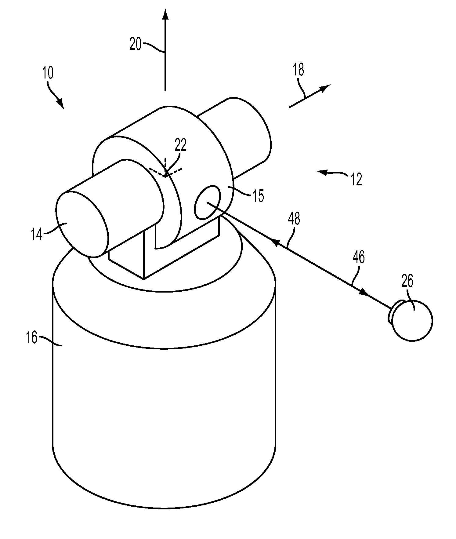
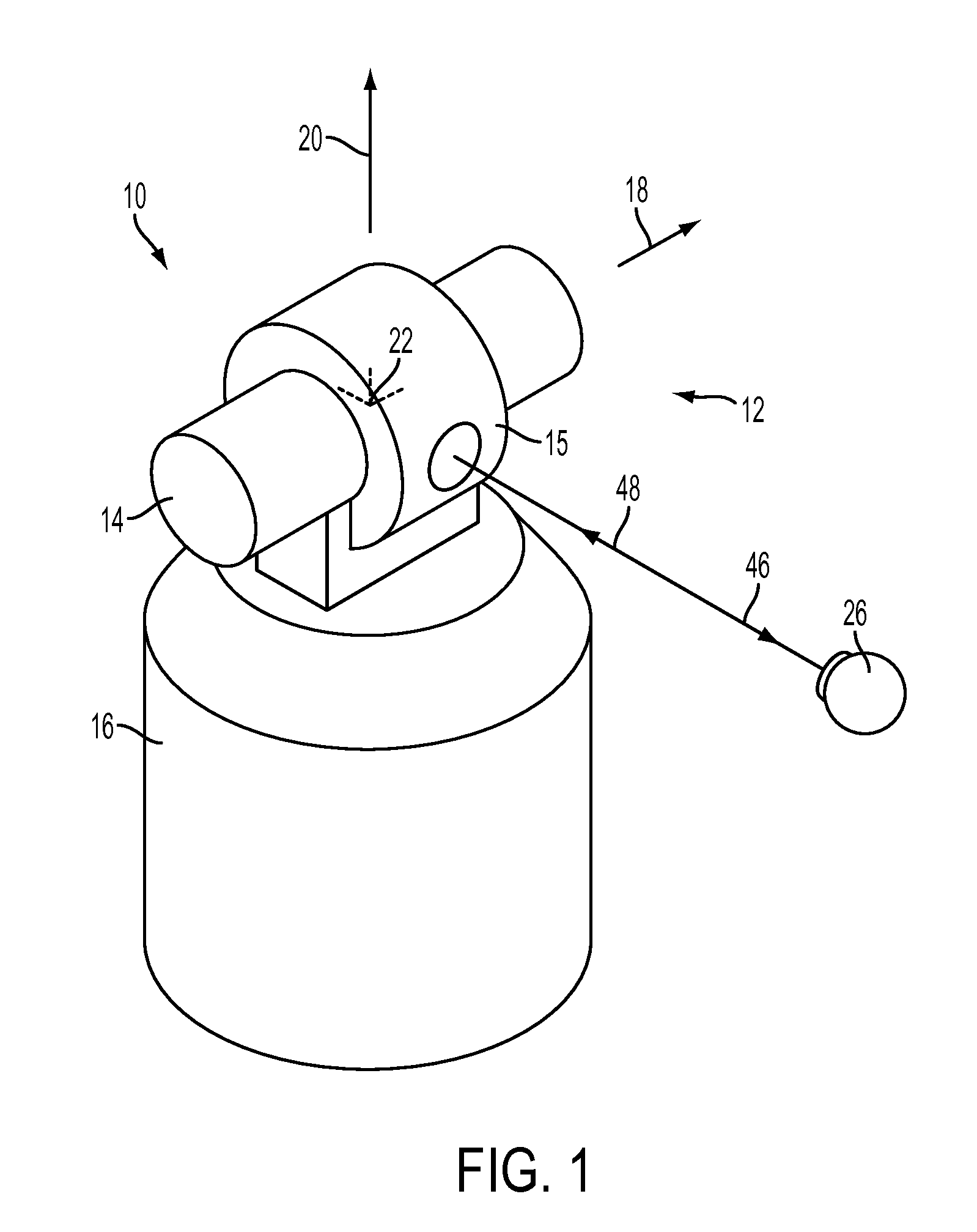
FIG. 1 illustrates a laser tracker 10 that may be used with the apparatus and method for measuring hidden points as described herein. The laser tracker 10 sends a laser beam 46 from the laser tracker 10 to SMR 26, which returns the laser beam 48 to tracker 10. Laser beam 48 is slightly reduced in optical power with respect to laser beam 46 but otherwise is nearly identical to laser beam 46. An exemplary gimbaled beam-steering mechanism 12 of laser tracker 10 includes zenith carriage 14 mounted on azimuth base 16 and rotated about azimuth axis 20. Payload 15 is mounted on zenith carriage 14 and rota...


PUM


Abstract

Exemplary embodiments include a sphere bar probe apparatus, including a holder, a retroreflector disposed in the holder, a member having a first end and a second end, wherein the first end is attached to the holder and an end plate attached to the second end of the member.

Description

FIELD OF INVENTIONThe present invention relates to retroreflector measurement, and more particularly to apparatus and methods enabling a spherically mounted retroreflector to be used with a laser tracker to measure hidden points.BACKGROUNDThere is a class of instrument that measures the coordinates of a point by sending a laser beam to a retroreflector target in contact with a point on an object. The instrument determines the coordinates of the point by measuring the distance and the two angles to the target. The distance is measured with a distance-measuring device such as an absolute distance meter or an interferometer. The angles are measured with an angle-measuring device such as an angular encoder. A gimbaled beam-steering mechanism within the instrument directs the laser beam to the point of interest.The laser tracker is a particular type of coordinate-measuring device that tracks the retroreflector target with one or more laser beams it emits. Another instrument known as tota...

Claims


Application Information

Patent Timeline
IPC IPC(8): G01B11/24
CPCG01B11/026G01B11/24G01S17/66G01S17/42G01C15/002G01B11/002G01B11/30G01C15/06
Inventor EDMONDS, PETERSTEFFEY, KENNETH
Owner FARO TECH INC
Why Eureka
Try Eureka