Dual accelerometer detector for clamshell devices

Inactive Publication Date: 2011-07-28
STMICROELECTRONICS SRL
View PDF2 Cites 150 Cited by
  • Summary
  • Abstract
  • Description
  • Claims
  • Application Information

AI Technical Summary

Problems solved by technology

Removal of simple switches is also desirable due to single point failure, wear, and reliability issues.

Method used


Image

  • Dual accelerometer detector for clamshell devices
  • Dual accelerometer detector for clamshell devices
  • Dual accelerometer detector for clamshell devices

Examples


Embodiment Construction

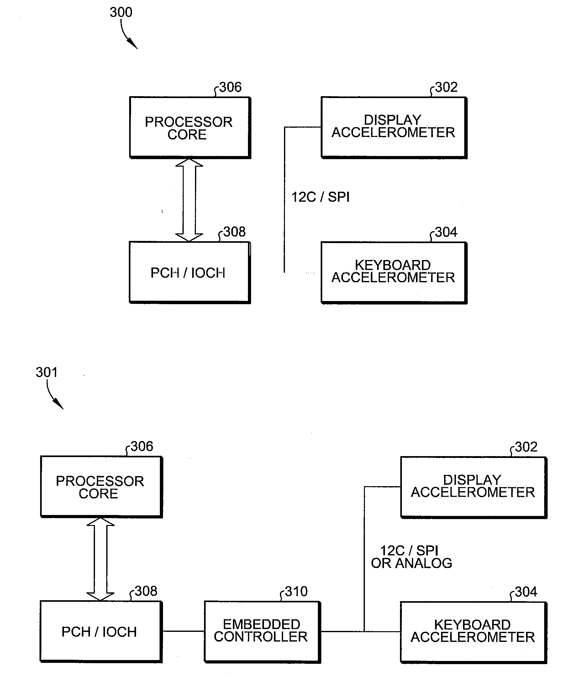
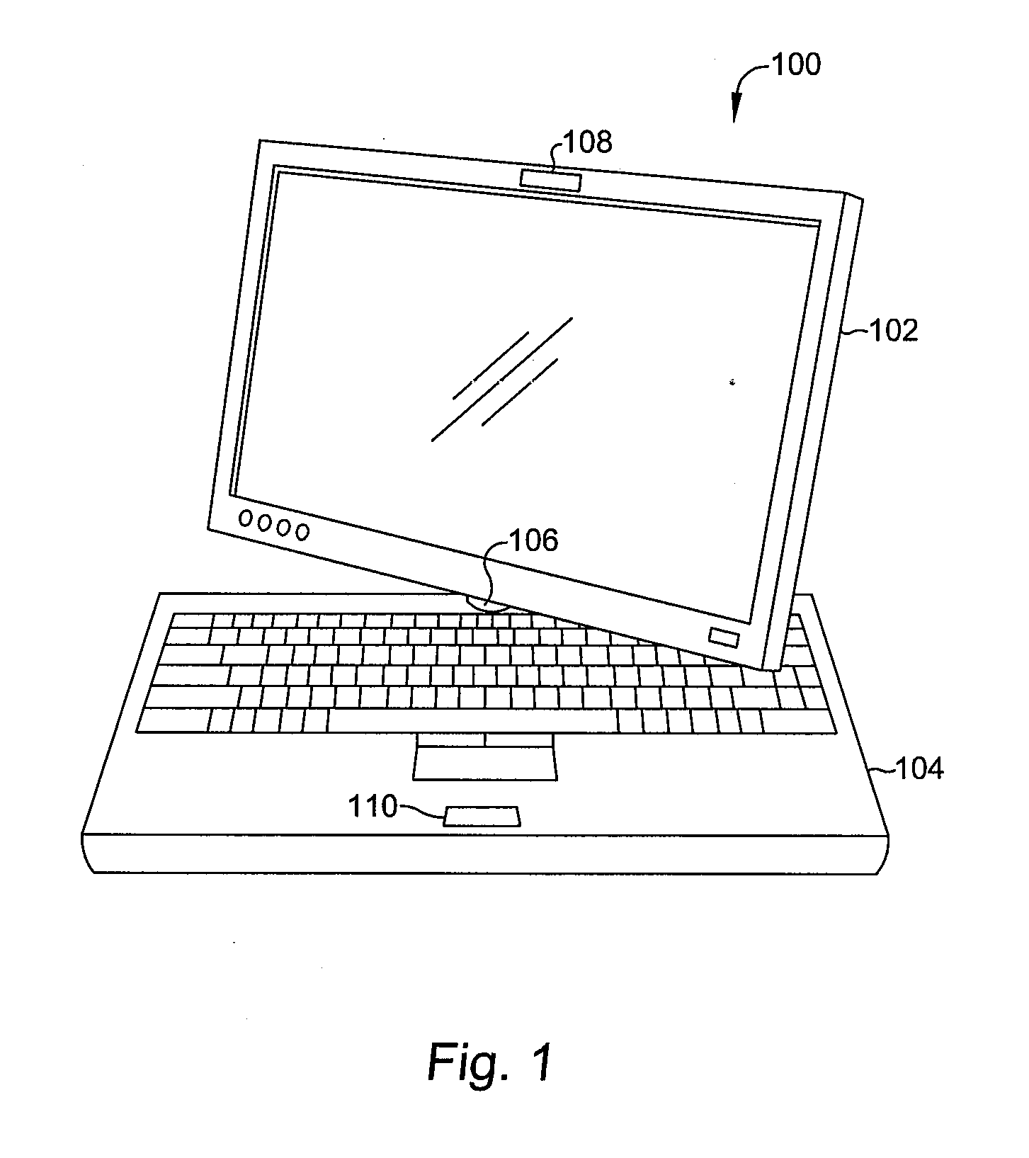
[0020]Referring now to FIG. 1, a clamshell device, in this case a personal computer, is shown having a first display portion 102 and a second keyboard portion 104, joined by a swivel hinge 106, as is known in the art. To accomplish the detection function of the present invention, a first accelerometer 108 is located in a fixed, known orientation in the display portion 102, such as embedded in the camera module. The second accelerometer 110 is placed in a fixed, known orientation on the second keyboard portion 104 located on, or operatively in communication with, the motherboard of the computer.

[0021]The first and second accelerometers should be three axis capable accelerometers with either an analog or digital output.

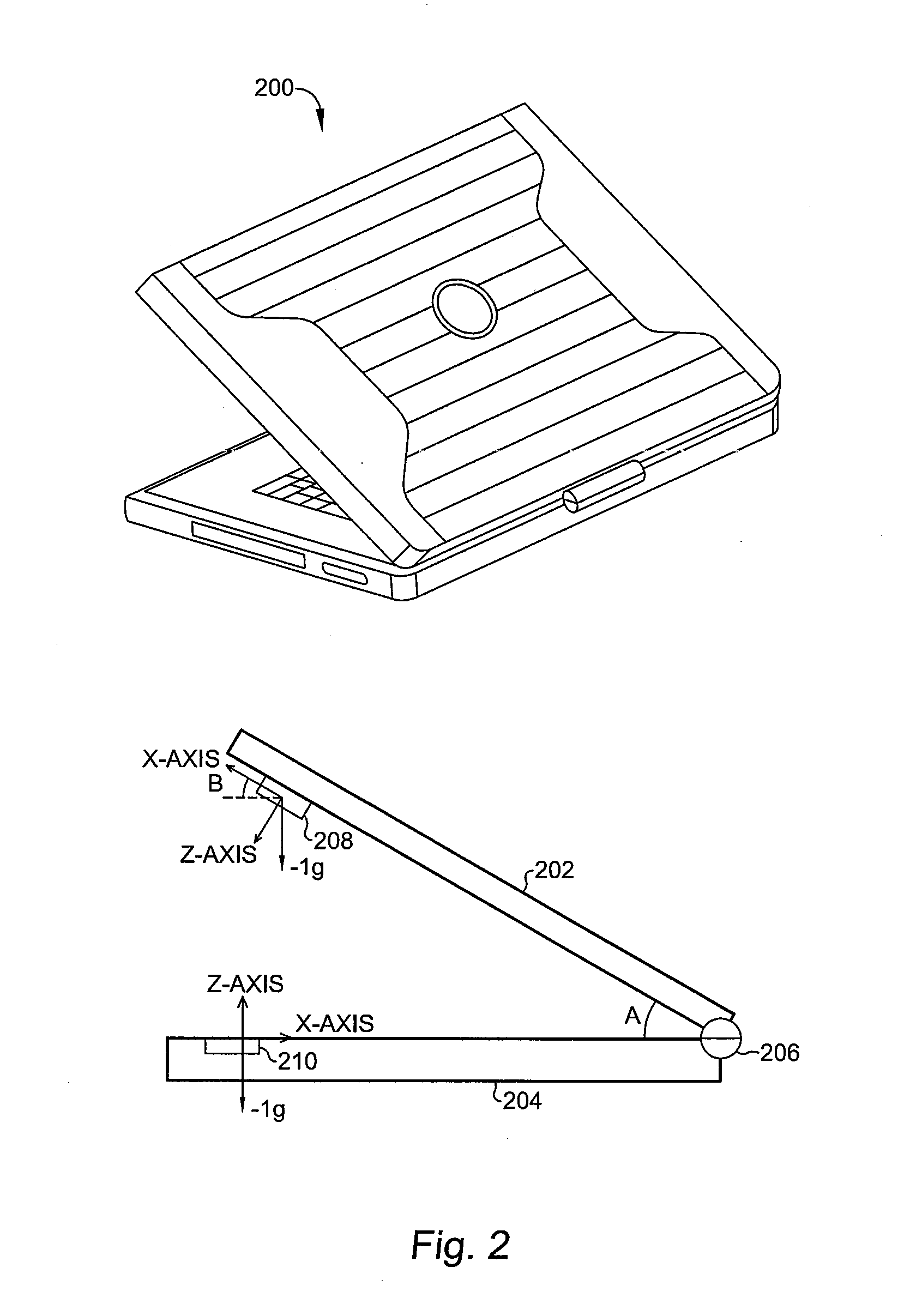
[0022]Referring now to FIG. 2, the personal computer 200 is shown in a position where neither the keyboard can be accessed nor can the display be properly viewed. In this example, the keyboard 204 is horizontal, and perpendicular with the Z-axis of accelerometer 210 Thi...


PUM


Abstract

A clamshell device having a dual accelerometer detector includes a first keyboard portion including a first accelerometer, a second display portion including a second accelerometer, a hinge for coupling the first portion to the second portion, and circuitry coupled to the first and second accelerometers for providing an output signal in response to the position of the first and second portions of the clamshell device. The output signal is provided to indicate a shutdown or standby mode, tablet operation mode, a partially shut or power savings mode, a normal operating mode, or an unsafe operating mode.

Description

BACKGROUND OF THE INVENTION[0001]The present invention is related to clamshell devices and, more particularly, to a dual accelerometer detector for a clamshell device.[0002]Today's mobile devices that have clamshell designs use a Hall sensor / magnet combination or switches to determine when the lid / display is closed. Examples of such mobile devices known in the art are cell phones, notebook computers, netbooks, and tablet personal computers, among many other such devices.[0003]The “open / close” sensors contained in these devices are used to determine the state the device is in and impacts the operational mode of the device. For example, in notebook computers, when the device is closed, the LCD panel backlight is typically shut off. Closing the device can also cause a sleep or hibernation mode to be activated.[0004]Magnetometers (electronic compass) are now being added into these mobile clamshell devices to assist in various new navigation applications. Removal of the existing Hall sen...

Claims


Application Information

Patent Timeline
Patent Type & Authority Applications(United States)
IPC IPC(8): G01P1/00
CPCG06F1/1616G06F1/162G11B19/043G06F1/3203G11B19/042G06F1/1677
Inventor RAASCH, WILLIAM R.LIN, WENBENDISCIOLI, PAOLORESSIA, ALBERTO
Owner STMICROELECTRONICS SRL
Why Eureka
Try Eureka