
Baseball bat employing a dual density foam material

a dual-density foam and bat frame technology, applied in the field of baseball bats and softball, can solve the problems of reducing the responsiveness of the bat, affecting compromising the hitting performance of less skilled players, so as to reduce the vibration, dampen even small deflections of the baseball bat frame, and increase the barrel response

Inactive Publication Date: 2011-07-28
MATTINGLY SPORTS
View PDF11 Cites 3 Cited by
  • Summary
  • Abstract
  • Description
  • Claims
  • Application Information

AI Technical Summary

Benefits of technology

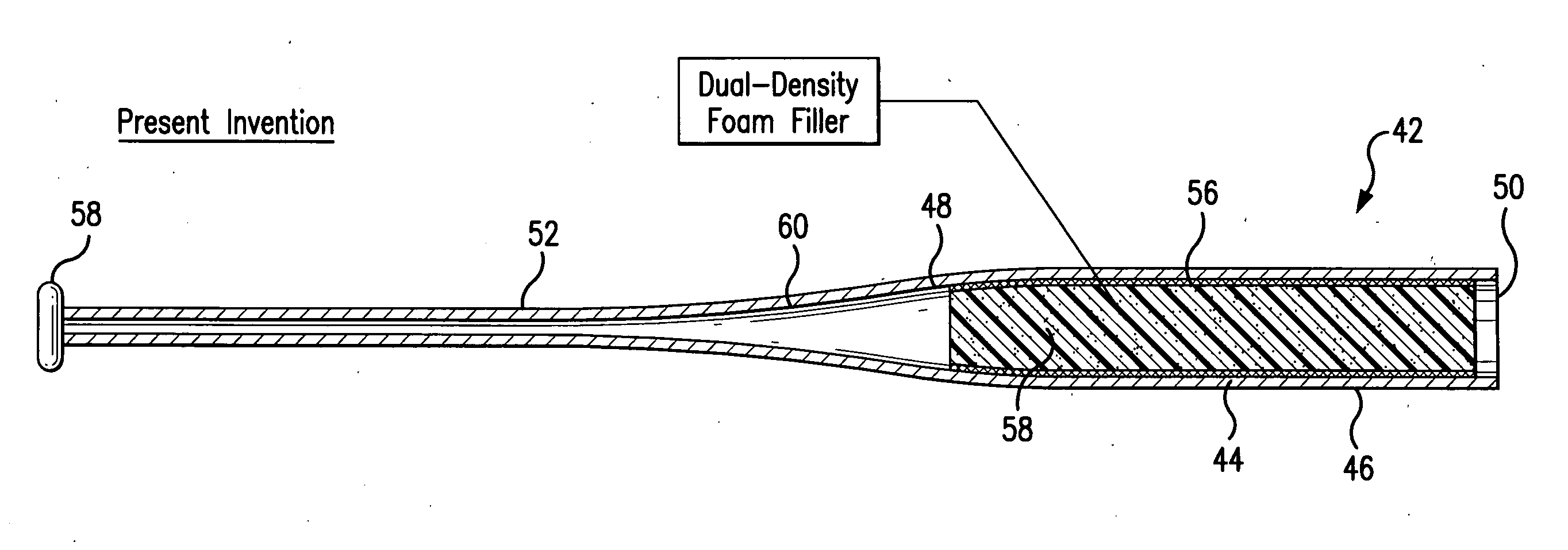
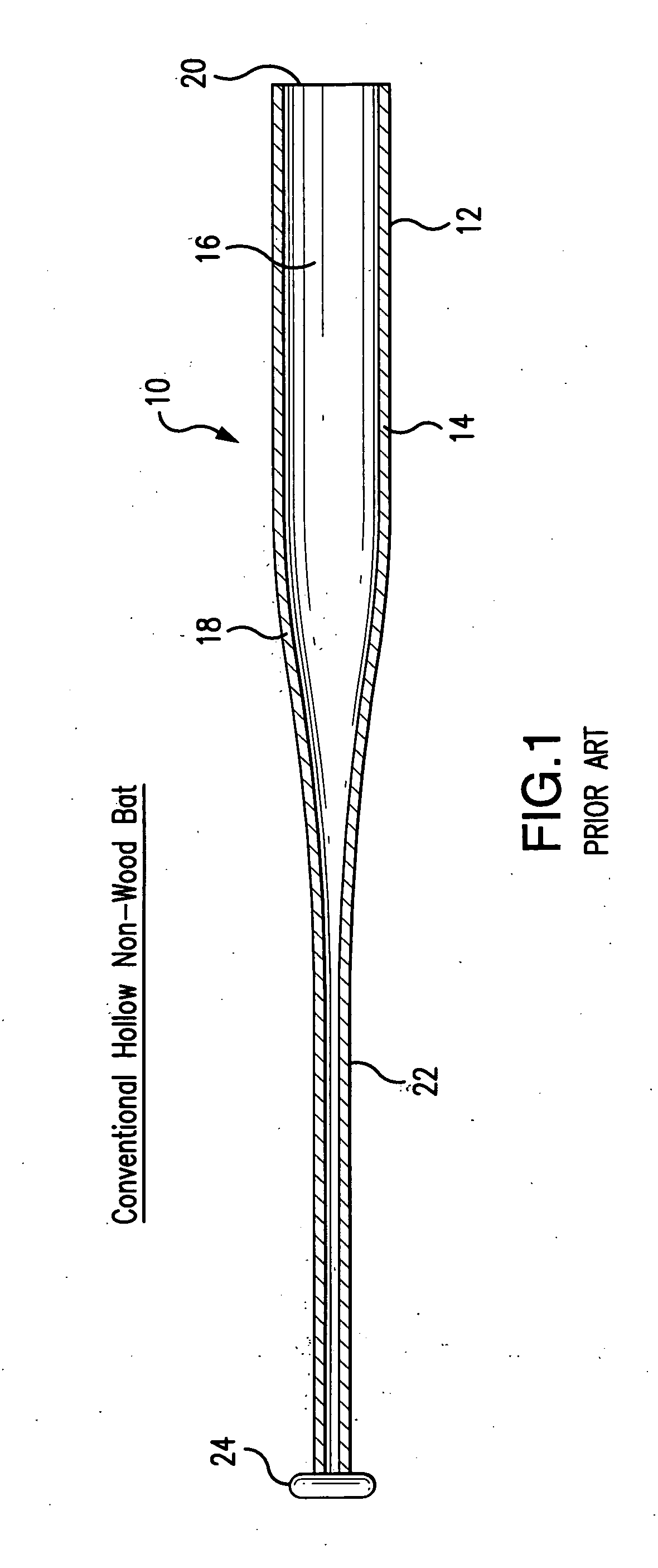
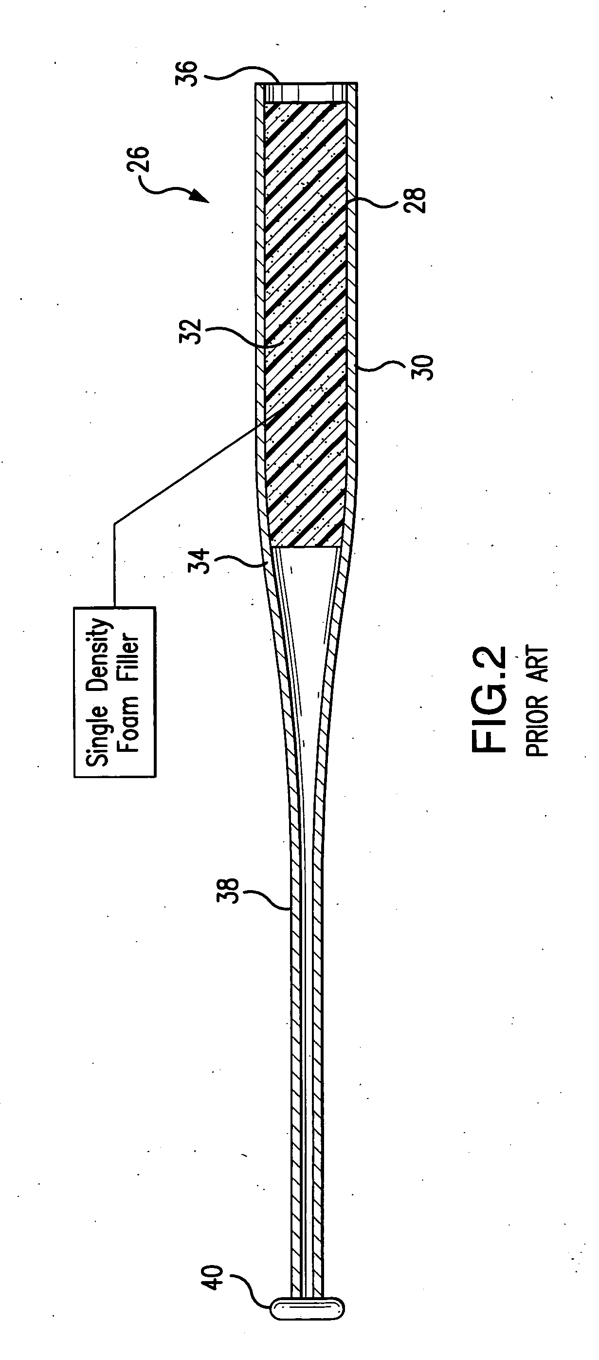
[0013]The deficiencies of the prior art are addressed by the present invention in which a non-wood baseball or softball bat is produced utilizing an insert with a highly compressible outer foam layer which allows the bat frame to deflect within a limited range with minimal dampening of the vibrations produced when a ball strikes the outer surface of the baseball or softball bat. The prior art use of a single density material such as described in the aforementioned Felice patents would dampen even small deflections of the baseball bat frame. The present invention would allow a greater barrel response (commonly referred to as the “trampoline effect”) for lower speed impacts verses the prior art, while still limiting the maximum barrel response for higher speed impacts produced by the best players. This would allow the bat to meet the required safety standards by the various governing bodies, but still providing an improved hit performance for the less skilled players.
[0014]Additionally, the present invention is also an improvement of the prior art bats utilizing a dual density material such as described in the aforementioned Baum patents. As previously indicated, the Baum patents employ a core material formed from a resilient urethane foam which is denser and therefore less compressible than the plug material which it surrounds. This is in contradistinction to the present invention utilizing two separate foams of different density. A first foam material is provided in the interior of the bat extending from the end cap to approximately the beginning of the tapered portion of the bat. This material is surrounded by a thin layer of a foam material having a density less than the density of the inner foam material. Consequently, the thin outer layer of the foam is much more compressible than the inner foam layer. This particular configuration would provide for a better performance at low impact speeds than the prior art bats utilizing a single foam material.

Problems solved by technology

Unfortunately, each of these prior attempts has various shortcomings.
In other words, these designs reduce the responsiveness of the bat at both low impact speeds as well as high impact speeds.
This approach hinders the hitting performance of less skilled players in an effort to control the maximum rebound speed generated by the best players.
However, it has been found that the aforementioned designs would produce a bat in which the hitting performance of the less skilled players might be compromised in the effort to control the maximum rebound speed generated by the best players.

Method used


Image

  • Baseball bat employing a dual density foam material
  • Baseball bat employing a dual density foam material
  • Baseball bat employing a dual density foam material

Examples


first embodiment

[0023]FIGS. 3 and 4 illustrate the present invention. These figures show a non-wood bat 42 including a barrel section 44 provided with an outer surface 46, an end cap 50, a handle 52 and a tapered section 48 extending between the barrel 44 and the handle 52. Similar to prior art bats, an end knob 54 would be provided at the end of the handle section 52. The entire interior section of the barrel 44 would be filled with two different types of foam material. The majority of the interior section of the barrel 44 would be filled with a relatively low compression inner foam material 58. The tapered portion 48 and the handle portion 52 are not filled with the foam material and remain hollow for their entire length as shown by 60.

[0024]This inner foam material 58 would be surrounded by a thin highly compressible outer foam layer 56. The outer highly compressible foam layer 56 could be constructed from an open cell polyether or polyester foam having a compressive deflection of less than one ...

second embodiment

[0025]FIG. 5 illustrates the present invention which primarily illustrates the barrel portion 62 having an outer surface 64 of the bats illustrated with respect to FIGS. 3 and 4. Similar to FIGS. 3 and 4, the portion of the bat illustrated with respect to FIG. 5 would include a relatively low compressibility foam layer 68 surrounded by a relatively high compressibility layer 66. However, as illustrated with respect to FIGS. 3 and 4, the thickness of the outer foam layer 58 and the outer foam layer 56 is constant over the length of the barrel 44. This is to be distinguished from the barrel 62 in which the thickness of the outer foam portion 66 and the inner foam portion 68 would gradually vary over the length of the barrel 62. For example, the thickness of the outer foam layer 66 is smallest at approximately the middle portion of the bat 72. The diameter of the outer foam layer 66 would gradually increase as it moves from the section 72 to section 70 as it approaches the end cap of t...


PUM


Abstract

A non-wood baseball or softball bat wherein the barrel portion of the bat is filled with an inner foam layer which has a relatively low compressibility surrounded by an outer foam layer having high compressibility. This configuration would not hinder the hitting performance of less skilled players in an effort to control the maximum rebound speed generated by the best players.

Description

FIELD OF THE INVENTION[0001]The present invention is generally related to the field of baseball and softball and more specifically to a baseball or softball bat.BACKGROUND OF THE INVENTION[0002]Baseball and softball players continually search for better bats to improve their hitting performance. Bat performance is generally based upon length, weight, moment of inertia (MOI) and impact response during contact with the ball. Manufacturers have made attempts to improve the impact response during contact with the ball using a variety of material construction. Unfortunately, each of these prior attempts has various shortcomings.[0003]As manufacturers have improved bats, various regulatory bodies and administrators of organized baseball and softball games have placed restrictions on bat performance and configuration. In order to limit the maximum response to the bat, manufacturers have traditionally modified their designs to dampen the response to all impacts. In other words, these design...

Claims


Application Information

Patent Timeline
Patent Type & Authority Applications(United States)
IPC IPC(8): A63B59/06
CPCA63B59/0092A63B2209/00A63B59/06A63B60/54A63B2102/18A63B59/50A63B2102/182A63B59/51A63B59/54
Inventor SMITH, CHUCK
Owner MATTINGLY SPORTS
Learn More