
Image forming apparatus

a technology of image forming apparatus and forming tube, which is applied in the direction of electrographic process apparatus, instruments, optics, etc., can solve the problems of insufficient triboelectric charge of toner, reducing the distance from the supply opening of toner to the developer carrying member, and lowering the charging performance. stable, reproducible image density, suitable for resource saving and electric power saving

Inactive Publication Date: 2011-08-11
CANON KK
View PDF7 Cites 10 Cited by
  • Summary
  • Abstract
  • Description
  • Claims
  • Application Information

AI Technical Summary

Benefits of technology

[0006]A principal object of the present invention is to provide a developing device capable of ensuring sufficient mixing and stirring and of ensuring triboelectric charging until a developer reaches a developer carrying member, even when toner and a carrier are supplied to a circulation path of the developer, without adding a dedicated feeding path. As a result, another object of the present invention is to provide an image forming apparatus in which the carrier which is only just supplied and is not deteriorated is less liable to be discharged from a discharge opening, in which a charging performance of the developer is stable and reproducibility of an image density is high, and which is suitable for resource saving and electric power saving.

Problems solved by technology

However, with respect to the two-component developer, the toner is replaced with fresh one by the supply and on the other hand, the carrier is continuously subjected to stirring and friction in the developing device, thus causing a problem such that a charging performance is gradually lowered.
Further, when the discharge opening of the developer is disposed on the upstream side of a supply opening of the toner, a distance from the supply opening of the toner to the developer carrying member is decreased, so that the toner is not triboelectrically charged sufficiently.
When the toner is not triboelectrically charged sufficiently, a problem of improper development or toner scattering is liable to occur.
When the developer which is mixed insufficiently and is in a non-uniform charged state is subjected to the development, the developer causes image defect such as density non-uniformity or fog.
However, a structure of the developing device is complicated and thus it is difficult to downsize the developing device and power consumption necessary for operation is increased.

Method used


Image

  • Image forming apparatus
  • Image forming apparatus
  • Image forming apparatus

Examples


embodiment 1

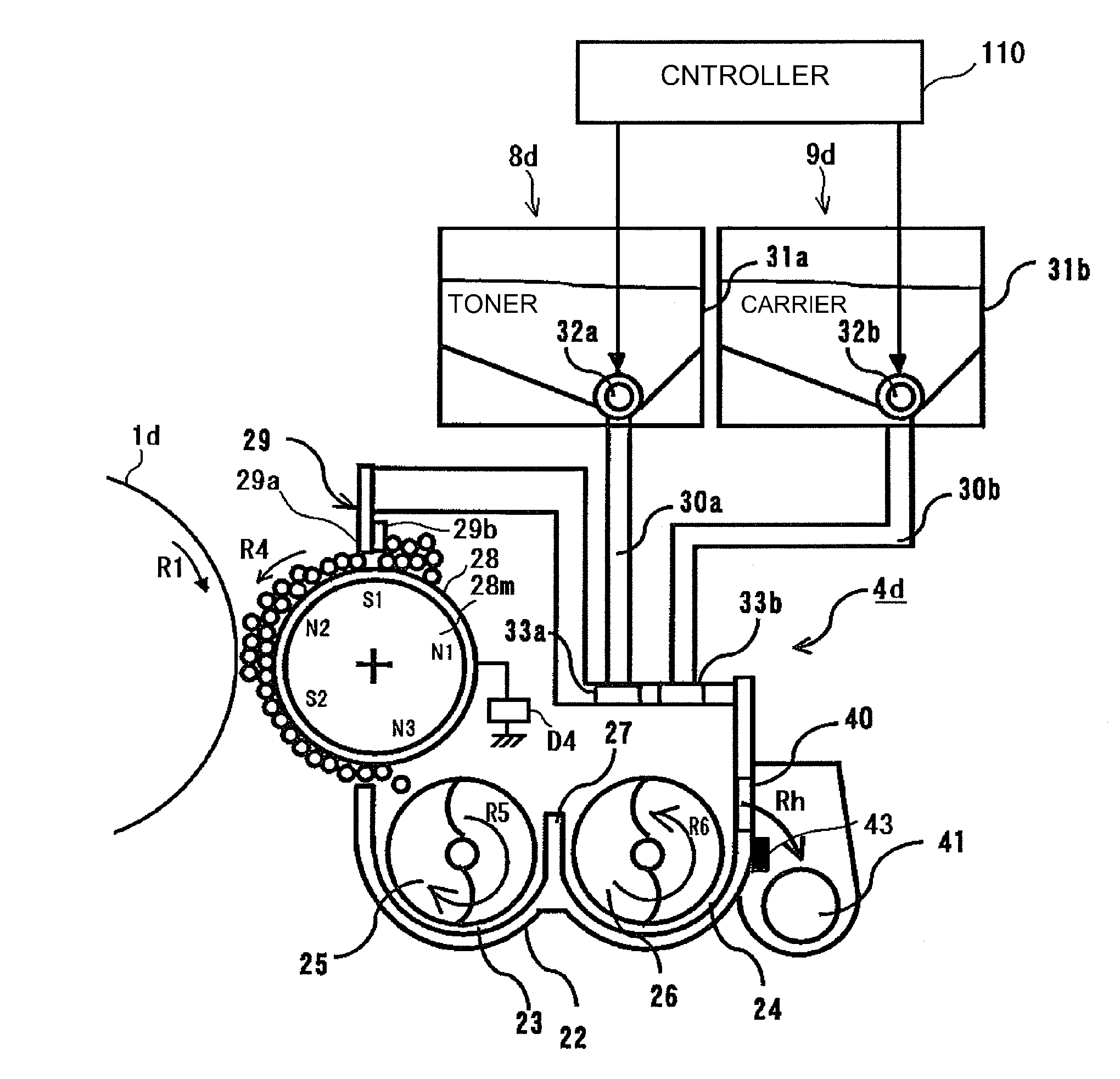
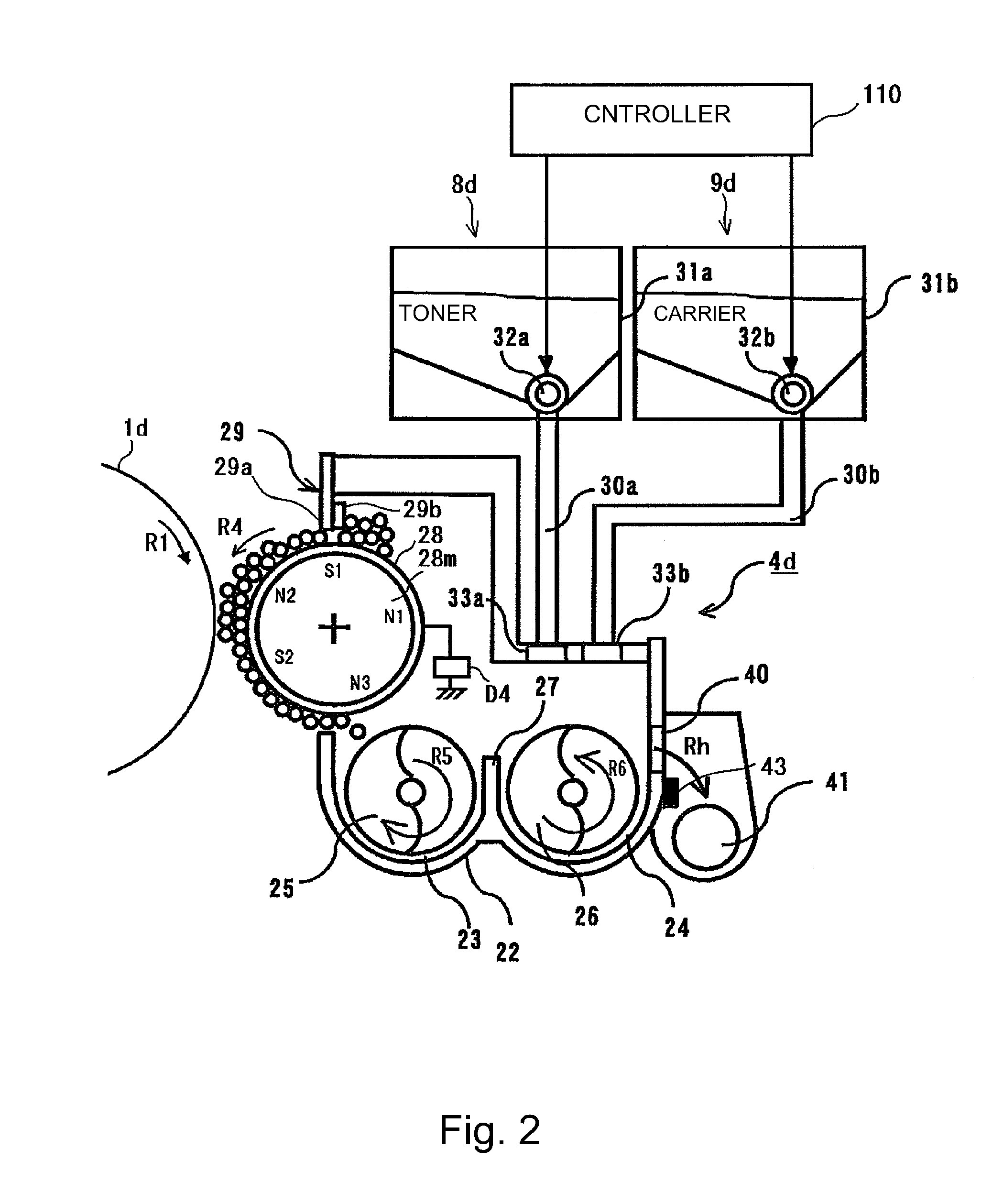
[0076]FIG. 4 is a block diagram of a control system of the developing device. FIG. 5 is a flow chart of carrier supply control. FIG. 6 is a graph for illustrating an effect of the carrier supply control.

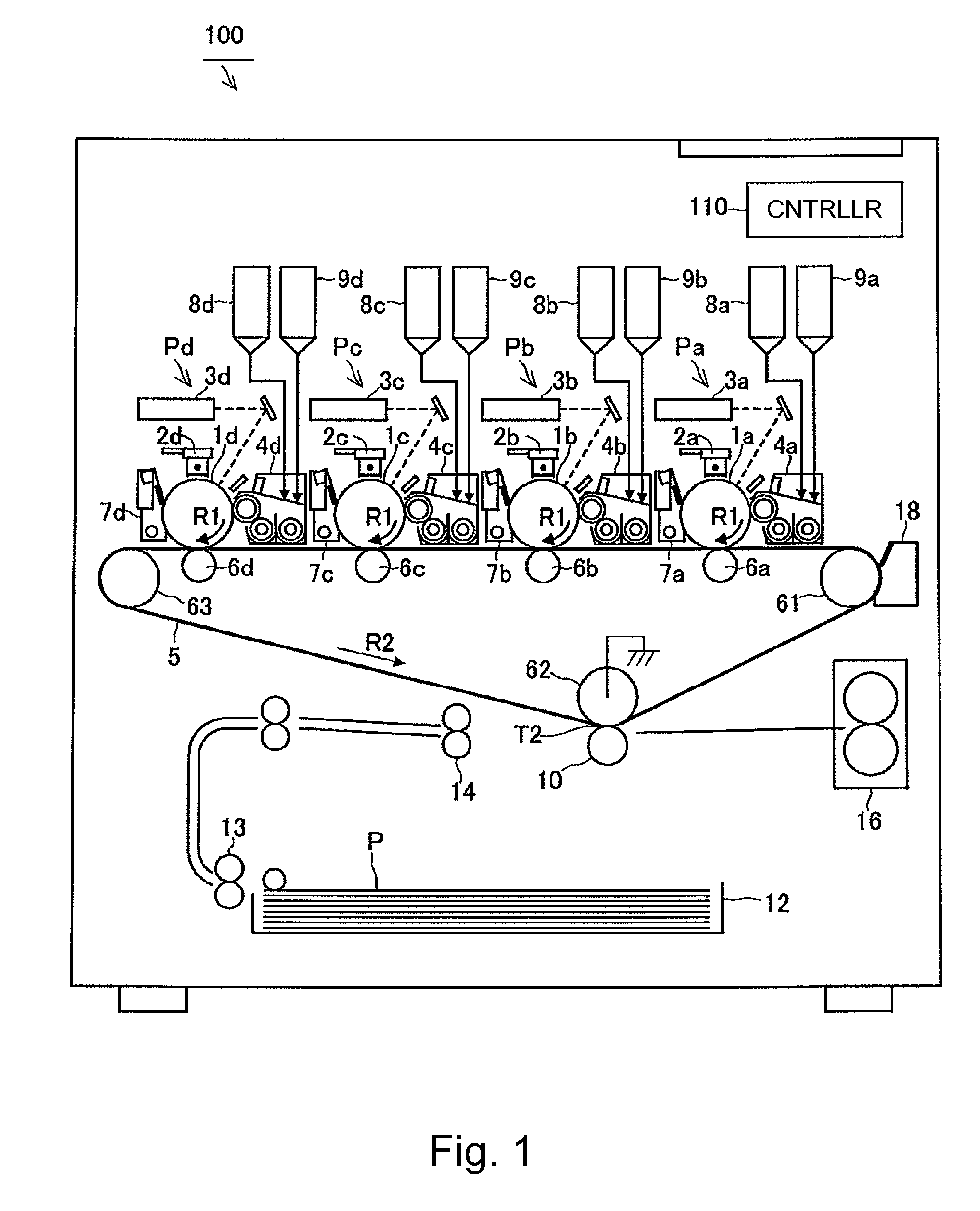
[0077]As shown in FIG. 2, at an upper portion of the developing device 4d, a toner supply portion 8d which is an example of the first developer supply device and a carrier supply portion 9d which is an example of the second developer supply device are connected.

[0078]The toner supply portion 8d supplies a first developer, having the toner ratio higher than that of the developer which circulates in the developing device 4d, to an upstream side end portion of the stirring chamber 24. In this embodiment, in a hopper 31a of the toner supply portion 8d, the supply developer containing the toner, in the weight ratio of 100%, identical to that in the developed filled in the developing device 4d is accommodated.

[0079]The toner supply portion 8d supplies the first developer to a position on t...

embodiment 2

[0120]FIG. 8 is an illustration of a structure of a developing device in Embodiment 2. FIG. 9 is a sectional view of the developing device in Embodiment 2 as seen from a side surface.

[0121]In Embodiment 2, the present invention is applied to a vertical type developing device in which the developing chamber 23 and the stirring chamber 24 are vertically disposed. The developing device in Embodiment 2 is provided in the image forming apparatus 100 by replacing the developing device 4d shown in FIG. 1 therewith. In this embodiment, in order to facilitate comparison with Embodiment 1, in FIGS. 8 and 9, members corresponding to those for the developing device 4d in Embodiment 1 are represented by the common reference numerals or symbols and will be omitted from redundant description.

[0122]As shown in FIG. 8, with respect to the vertical type developing device 4d, the developer (two-component developer) containing the toner and the carrier is accommodated in the developing container 22. In...


PUM


Abstract

A developing device includes a developer carrying member; a first feeding path in which a developer is to be supplied and fed to the developer carrying member at a position in which the first feeding path opposes the developer carrying member; a second feeding path, communicating with the first feeding path, for forming a circulation path with the first feeding path; a discharge opening for permitting discharge of an excessive developer in the developing device; a first supply opening, located downstream of the first feeding path opposing the developer carrying member with respect to a developer feeding direction and located upstream of the discharge opening with respect to the developer feeding direction, for permitting supply of a first developer containing at least toner; and a second supply opening, located upstream of the first feeding path with respect to the developer feeding direction and located downstream of the discharge opening with respect to the developer feeding direction, for permitting supply of a second developer which has a toner ratio lower than that of the first developer or is consisting only of a carrier.

Description

FIELD OF THE INVENTION AND RELATED ART[0001]The present invention relates to an image forming apparatus in which a developer is to be supplied to a circulation path of the developer and on the other hand, the developer which has been deteriorated is to be discharged from the circulation path through a discharge opening. More specifically, the present invention relates to disposition (arrangement) of the discharge opening and a supply position of the developer in a developing device.[0002]The image forming apparatus in which an electrostatic image formed on a photosensitive member is to be developed with a two-component developer containing (non-magnetic) toner and a (magnetic) carrier has been widely used. In a developing device using the two-component developer, the toner and the carrier are triboelectrically charged by circulating the developer in the circulation path disposed along a developer carrying member while stirring the developer. Then, the charged developer slides on the...

Claims


Application Information

Patent Timeline
Patent Type & Authority Applications(United States)
IPC IPC(8): G03G15/08
CPCG03G15/0877G03G15/0849G03G15/0893G03G15/0879G03G15/0856
Inventor INOUE, RYO
Owner CANON KK
Learn More