Candle Holder

a candle and holder technology, applied in the field of candle holders, can solve the problems of not being able to maintain the candle in a consistently upright position, the user has to either tilt the candle holder, and the wax drips often undetectedly out of the candle holder, so as to achieve the effect of more oxygen supply

Inactive Publication Date: 2011-08-18
FRANKLIN DAMON L
View PDF101 Cites 10 Cited by
  • Summary
  • Abstract
  • Description
  • Claims
  • Application Information

AI Technical Summary

Benefits of technology

[0010]An aperture is defined in the housing to receive the gimbal and the counterbalance. The counterbalance has an upper annular portion and a lower portion. In one embodiment, the counterbalance includes a recess formed in the upper annular portion. A groove is adapted in a top surface of the counterbalance to receive a magnetic disc. The candle includes a wick, a wax ring, a wick tab, and a cover, which is removably mounted on top of the magnetic disc in the annular top of the counterbalance. The aluminum cover advantageously prevents spillage of wax when the candle has been lit, while the magnetic properties of the wick tab create resistance for the candle to move away from the magnetic disc fixedly attached to the annular top of the counterbalance.
[0015]In yet another embodiment, the housing, at its distal end, contains one or more notches or apertures along its bottom edge and through one side of the housing that aid with heat dissipation for the candle holder. The notches can be any shape or configuration, such as, for example, arches, triangles, squares, rectangles (also referred to as parapets because of their similarity in appearance to the upper portion of a castle's wall), etc. Preferably, the notches are positioned along the surface of the housing opposite from which the enclosure is attached, creating a single or a series of openings through which air, heat and / or candle light can pass. The notches allow for additional air flow and more oxygen supply to the burning candle.
[0016]In another embodiment of the invention, the housing comprises a slide out tray pivotally connected to the housing. The slide out tray is rotationally connected to the housing with a pivot member such as a pin or hinge. Additionally, a groove or recess is included in the bottom surfaces of the tray and in the housing to receive a magnetic disc. The magnet discs help maintain the candle in the tray and the tray within the housing. This embodiment allows for the loading, lighting, and replacement of candles in the candle holder by sliding the tray out from its closed position, loading the candle, lighting it and returning the slide out tray to its original position within the housing.

Problems solved by technology

The disadvantage with these candle holders is that a user has to either tilt the candle holder or remove the candle from the holder in order to light it.
In such a situation, the wax often undesirably drips out of the candle and out of the candle holder, sometimes onto the user's fingers or the surrounding counter or floor area.
When the user carries the currently known hurricane candle, it is not possible to maintain the candle in a consistently upright position due to shifts caused by the user's movement and / or the inconsistency of the surface being traversed.
When a candle is not in a consistently upright position, there is always a chance for wax to drip out and / or over one's fingers which could result in the fingers getting burnt.
The design of candle holders known in the prior art do not provide for a means of catching molten wax that may spill from the candle.
Such an accidental occurrence could create the risk of a fire.
The disadvantage of a candle holder with that configuration is that, given its limited ability to pivot the fixture about only a single axis, it cannot consistently maintain the candle in the upright position when the orientation of the candle holder changes in a direction inconsistent with the axis for rotation of the fixture.
Additionally, because the fixture is centrally mounted within the glass enclosure, the difficulties with accessibility remain unaddressed.
Also, the shape of the glass tube and the positioning of the candle within the glass tube only allow for heat dissipation from the top of the tube when the candle holder is placed on a flat surface.
One last disadvantage of a candle holder with this configuration is that the glass tubes also functions as the supporting base.
Depending on the texture and hardness of the surface or the degree or care utilized when handling the candle holder, the glass could become scratched, chipped or even break when put down onto a surface.

Method used


Image

  • Candle Holder
  • Candle Holder
  • Candle Holder

Examples


Embodiment Construction

[0043]Although specific terms are used in the following description for the sake of clarity, these terms are intended to refer only to a particular structure of the invention selected for illustration in the drawings, and are not intended to define or limit the scope of the invention.

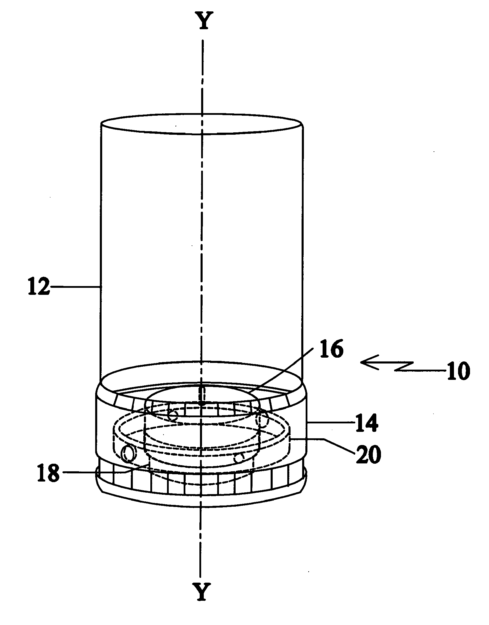
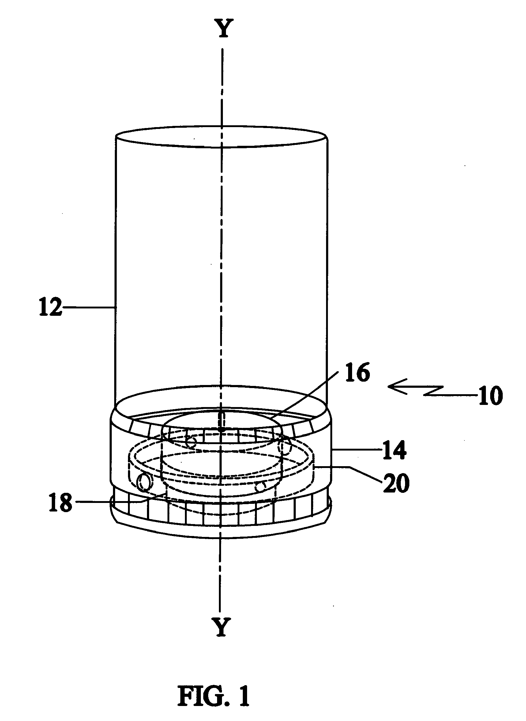
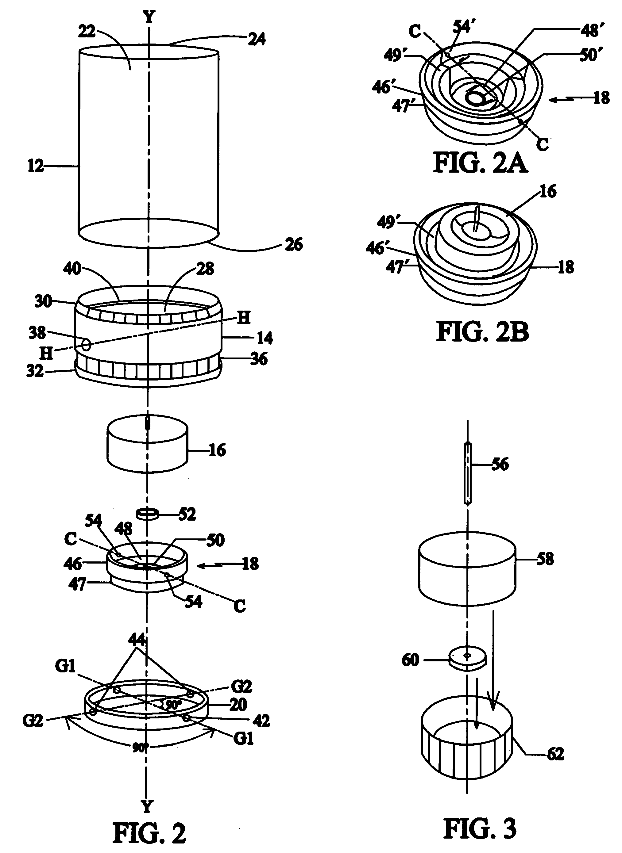
[0044]Referring to FIG. 1, a candle holder 10 in accordance with a preferred embodiment of the present invention is shown. The candle holder 10 includes an enclosure, envelope or cover 12 and housing 14. The enclosure 12 made of glass, stone or other noncombustible material used for candle holders or enclosures is fixedly and securely coupled with the housing 14. The housing 14 includes a candle 16 (although the candle itself need not be included as an integral part of the device) that is removably and securely positioned in a counterbalance 18. The counterbalance 18 is pivotally positioned in a gimbal 20 that is pivotally positioned in the housing 14. The candle holder 10 has a first upright position a...


PUM


Abstract

A candle holder that allows for the installed candle to be lit without having to remove the candle from the holder and that maintains the candle in an upright orientation as the orientation of the candle holder is varied. The candle holder includes a housing fixedly connected to an enclosure, the housing comprising, in one embodiment, a counterbalance with an annular top adapted to receive the candle. The present invention is also a candle holder with a pivotally connected candle tray that slides out of the housing to access the candle.

Description

CROSS-REFERENCE TO RELATED APPLICATIONS[0001]This application is a continuation-in-part of, and claims the benefit of U.S. patent application Ser. No. 12 / 152,972, filed on May 20, 2008, which claims the benefit of U.S. Provisional Patent Application Ser. No. 61 / 070,810, filed on Mar. 27, 2008, both of which are expressly incorporated herein in their entireties by reference thereto.BACKGROUND OF THE INVENTION[0002]1. Field of the Invention[0003]The present invention relates to a candle holder, and more particularly, to a candle holder having a housing including a pivoting counterbalance capable of maintaining a candle in an upright position when the candle holder is rotated. The present invention is also a candle holder having a housing including a pivoting counterbalance and a gimbal capable of maintaining a candle in an upright position when the candle holder is rotated. The present invention is also a candle holder having a housing including a slide out candle tray for the candle ...

Claims


Application Information

Patent Timeline
Patent Type & Authority Applications(United States)
IPC IPC(8): F21V35/00F23D3/18
CPCF21S13/12F23D3/18F21V35/00
Inventor FRANKLIN, DAMON L.
Owner FRANKLIN DAMON L
Why Eureka
Try Eureka