Rotary Cutting Unit With Deflection Baffle

a rotary cutting unit and deflection technology, applied in the direction of mowers, agriculture tools and machines, etc., can solve the problems of high stress point on the tip of the blade, unusable laying down and rolling, cracking or excess vibration, etc., to achieve not restrict or compromise the performance of the unit, not cause undesirable stress and/or strain, and not counteract the lift

Active Publication Date: 2011-08-25
DEERE & CO
View PDF14 Cites 1 Cited by
  • Summary
  • Abstract
  • Description
  • Claims
  • Application Information

AI Technical Summary

Benefits of technology

[0009]The deflection baffle keeps clippings flowing in a manner that does not restrict or compromise the performance of the unit, does not counteract the lift provided by the cutting blade, and does not cause undesirable stress and/or

Problems solved by technology

This can result in an undesirable laying down and rolling over effect on the grass.
This also can result in a high stress pressure point on the tip of the blade, which may contribute to loosening of the blade from the spindle, cracking or excess vibration.
Additionally, conventional deflection baffles may cause clippings or other material to collect and compact in areas under the cutting unit, while i

Method used


Image

  • Rotary Cutting Unit With Deflection Baffle
  • Rotary Cutting Unit With Deflection Baffle
  • Rotary Cutting Unit With Deflection Baffle

Examples


Embodiment Construction

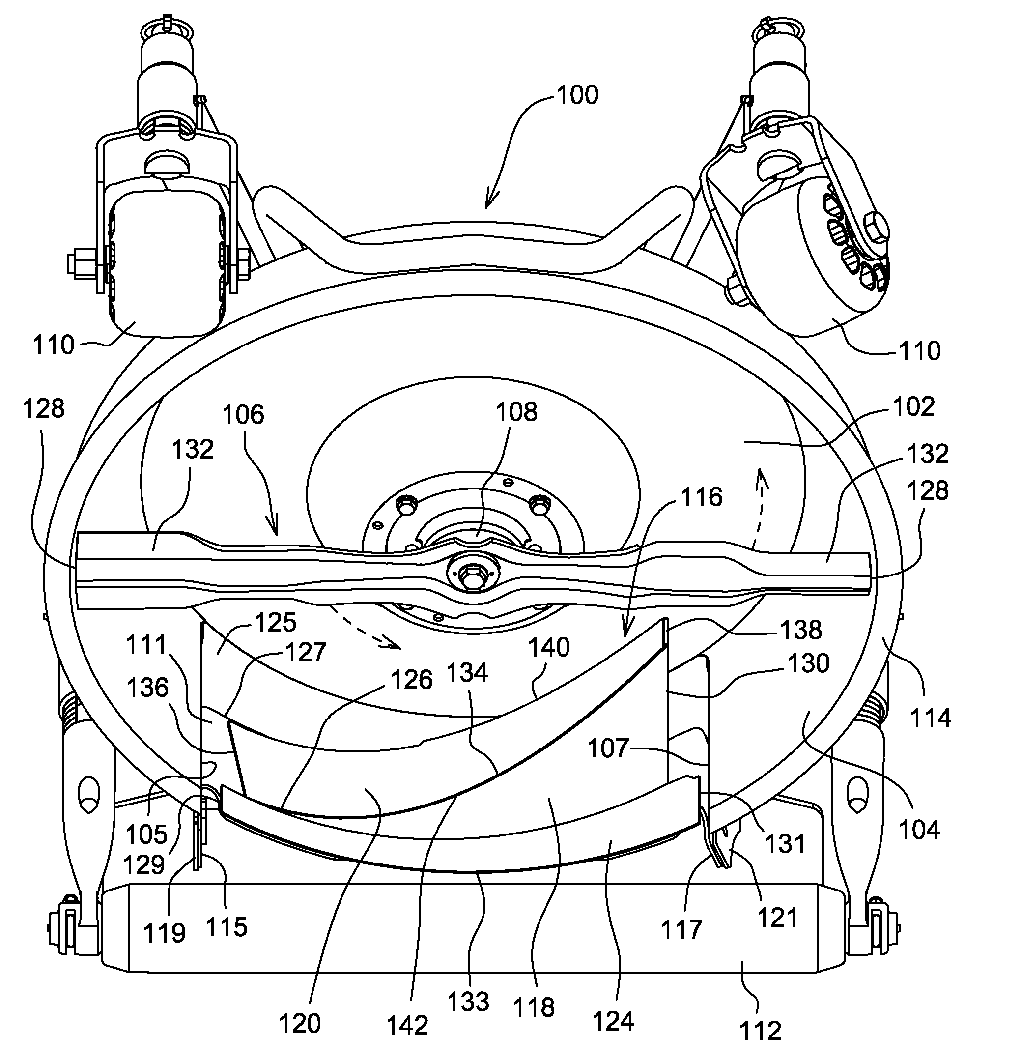
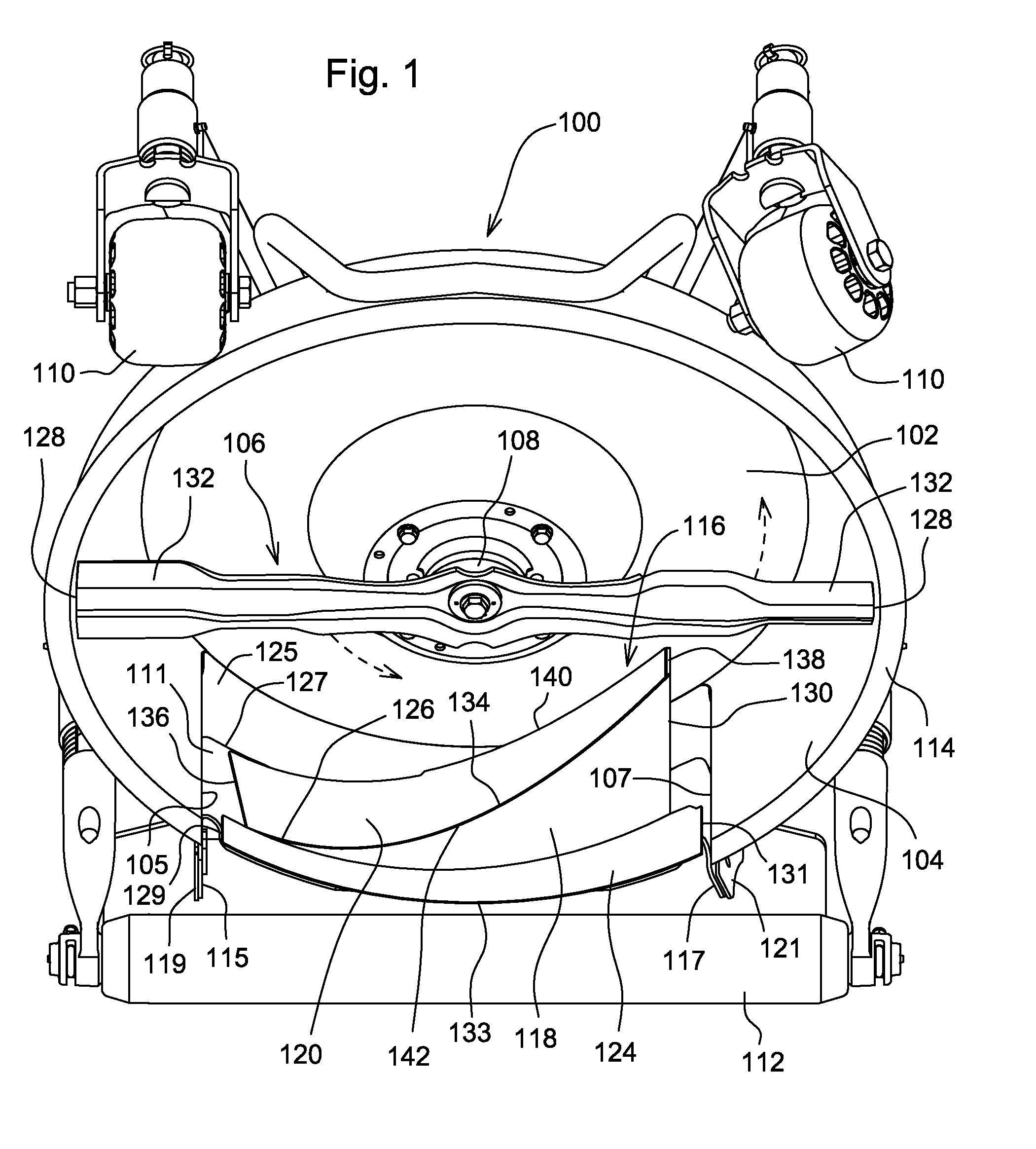
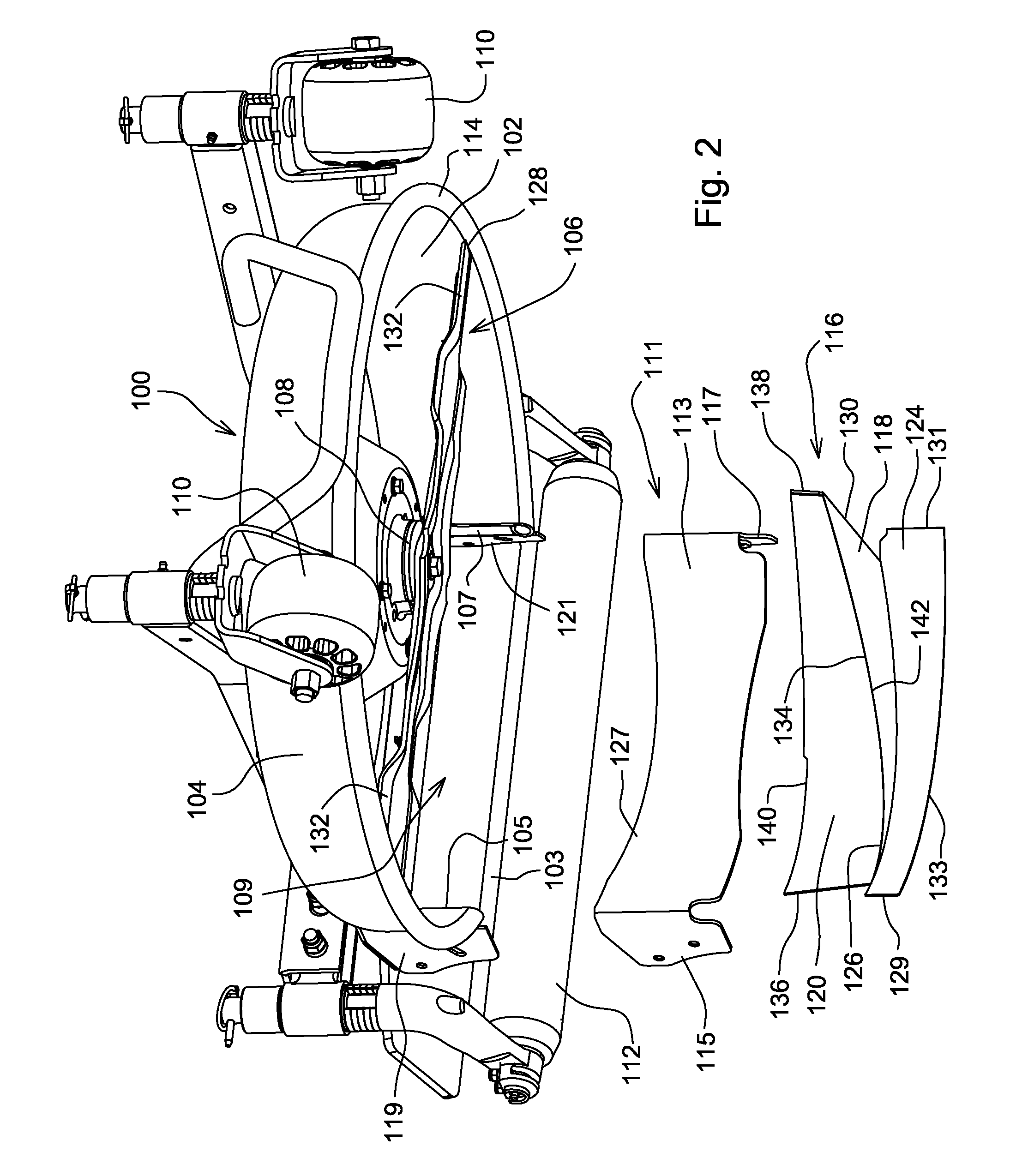
[0013]As shown in FIGS. 1-3, in a first embodiment, rotary cutting unit 100 may be carried by a traction vehicle for a rough mower. The rotary cutting unit includes a circular inverted dish-shaped shell or cutting chamber 102 with a downwardly extending outer perimeter wall 104 terminating at a lower edge or lip 114. A motor such as a hydrostatic motor may be mounted to the upper top surface of the rotary cutting unit. The motor turns a cutting blade 106 attached to a generally vertically aligned center spindle 108 in the shell or cutting chamber. The rotary cutting unit may be supported over the ground surface by a front pair of rollers 110, casters or wheels, and a rear roller 112. The rotary cutting unit may be pivotably supported at the end of a lift arm which the operator may actuate with one or more hydraulic cylinders or electric lift mechanisms to raise or lower the rotary cutting unit between a mowing position and a transport position.

[0014]In one embodiment, shell or cutti...


PUM


Abstract

A rotary cutting unit with a deflection baffle in the cutting chamber, the deflection baffle including a bottom plate attached to the wall at the rear of the cutting chamber and increasing in width in the direction of blade rotation, and a front plate joined to the bottom curved plate and extending from the wall at the rear of the cutting chamber and sloping radially inwardly toward the center spindle in the direction of blade rotation.

Description

FIELD OF THE INVENTION[0001]The present invention relates to a rotary cutting unit with a deflection baffle, and specifically to a rotary cutting unit with a deflection baffle that enhances the flow of grass clippings and minimizes stress on the cutting blade and spindle during mowing.BACKGROUND OF THE INVENTION[0002]Many new and existing golf courses have narrowed their fairways and expanded their rough areas on either end of the fairways. Roughs requires less care than fairways, so narrowing the fairways allows golf course operators to lower their maintenance costs. For example, irrigation requirements may be reduced if only the fairways are watered. If grasses in the roughs are allowed to grow longer, those non-irrigated areas are less brown. Trees and other aesthetic features may be located in the roughs, because roots and shade can inhibit turf growth in the fairways.[0003]Golf course roughs must be maintained regularly using grass mowing machines that can mow the vegetation at...

Claims


Application Information

Patent Timeline
IPC IPC(8): A01D34/73A01D67/00
CPCA01D42/005A01D34/005
Inventor CAMPBELL, CHAD W.
Owner DEERE & CO
Why Eureka
Try Eureka